Nissan Frontier D40. Manual - part 365


  Index      Nissan     Nissan Frontier D40 (2010 year) - Service and Repair Manual


Search            


Content   ..  363  364  365  366   ..


Nissan Frontier D40. Manual - part 365


P0133 A/F SENSOR 1

EC-151

< COMPONENT DIAGNOSIS >

[QR25DE]

C

D

E

F

G

H

I

J

K

L

M

A

EC

N

P

O

3.

Disconnect mass air flow sensor harness connector.

4.

Restart engine and let it idle for at least 5 seconds.

5.

Stop engine and reconnect mass air flow sensor harness con-
nector.

6.

Make sure DTC P0102 is displayed.

7.

Erase the DTC memory. Refer to 

EC-47, "Emission-related

Diagnostic Information"

.

8.

Make sure DTC P0000 is displayed.

9.

Run engine for at least 10 minutes at idle speed.
Is the 1st trip DTC P0171 or P0172 detected?
Is it difficult to start engine?

Yes or No

Yes

>> Perform trouble diagnosis for DTC P0171 or P0172. Refer to 

EC-169

 or 

EC-174

.

No

>> GO TO 6.

6.

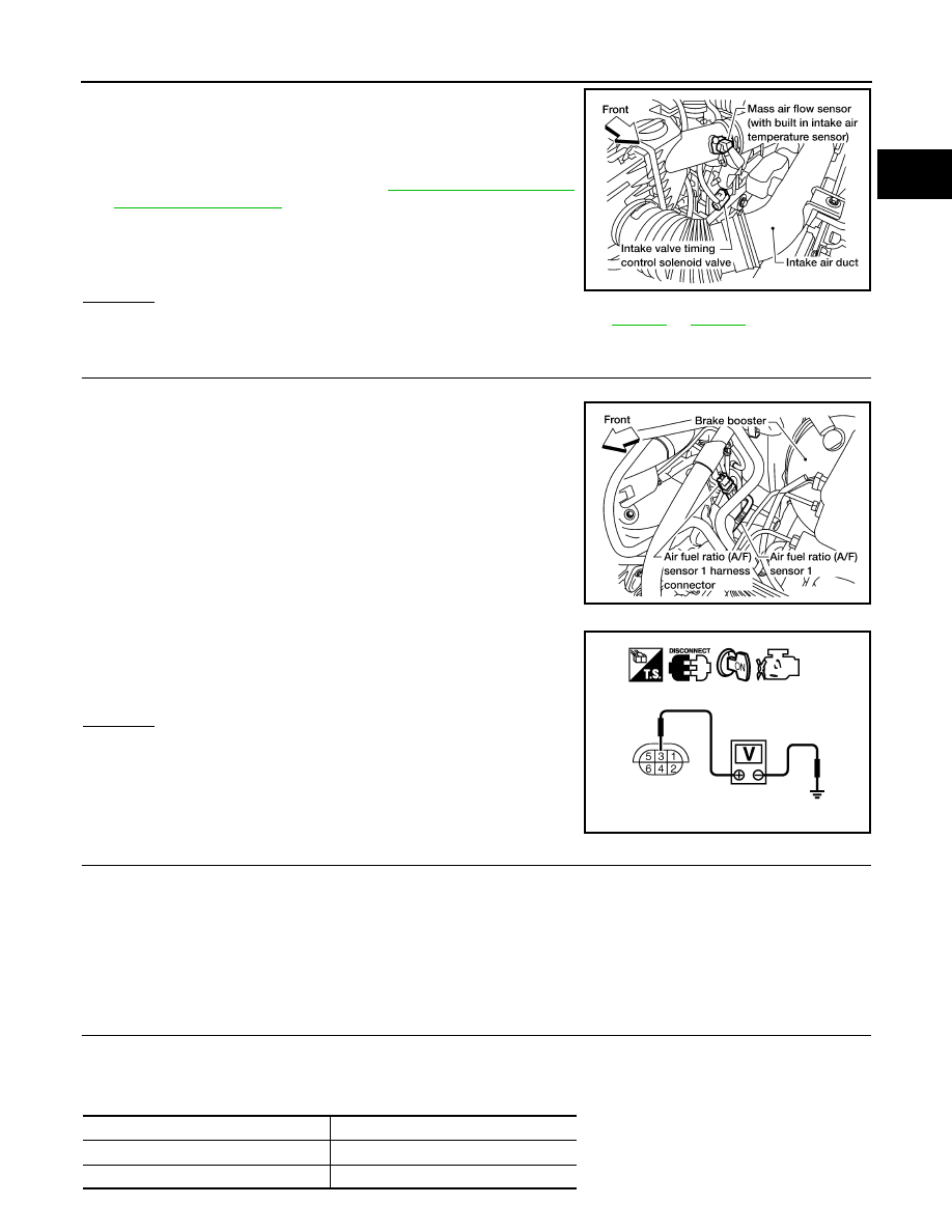
CHECK AIR FUEL RATIO (A/F) SENSOR 1 POWER SUPPLY CIRCUIT

1.

Turn ignition switch OFF.

2.

Disconnect A/F sensor 1 harness connector.

3.

Turn ignition switch ON.

4.

Check voltage between A/F sensor 1 terminal 3 and ground with
CONSULT-III or tester.

OK or NG

OK

>> GO TO 8.

NG

>> GO TO 7.

7.

DETECT MALFUNCTIONING PART

Check the following.
• Harness connectors E2, F32
• IPDM E/R harness connector E119
• 15A fuse (No.54)
• Harness for open or short between A/F sensor 1 and fuse

>> Repair or replace harness or connectors.

8.

CHECK A/F SENSOR 1 INPUT SIGNAL CIRCUIT FOR OPEN AND SHORT

1.

Turn ignition switch OFF.

2.

Disconnect ECM harness connector.

3.

Check harness continuity between the following terminals. Refer to Wiring Diagram.

BBIA0622E

BBIA0617E

Voltage: Battery voltage

PBIB1683E

A/F sensor 1 terminal

ECM terminal

1

16

2

75

EC-152

< COMPONENT DIAGNOSIS >

[QR25DE]

P0133 A/F SENSOR 1

4.

Check harness continuity between ECM terminals 16, 35, 56, 75 or A/F sensor 1 terminals 1, 2, 5, 6 and
ground. Refer to Wiring Diagram.

5.

Also check harness for short to power.

OK or NG

OK

>> GO TO 9.

NG

>> Repair open circuit, short to ground or short to power in harness or connectors.

9.

CHECK AIR FUEL RATIO (A/F) SENSOR 1 HEATER

Refer to 

EC-99, "Component Inspection"

.

OK or NG

OK

>> GO TO 10.

NG

>> GO TO 13.

10.

CHECK MASS AIR FLOW SENSOR

Refer to 

EC-110, "Component Inspection"

.

OK or NG

OK

>> GO TO 11.

NG

>> Replace mass air flow sensor.

11.

CHECK PCV VALVE

Refer to 

EC-392, "Component Inspection"

.

OK or NG

OK

>> GO TO 12.

NG

>> Repair or replace PCV valve.

12.

CHECK INTERMITTENT INCIDENT

Perform 

GI-46, "Intermittent Incident"

.

OK or NG

OK

>> GO TO 13.

NG

>> Repair or replace.

13.

REPLACE AIR FUEL RATIO (A/F) SENSOR 1

Replace air fuel ratio (A/F) sensor 1.

CAUTION:

• Discard any air fuel ratio (A/F) sensor which has been dropped from a height of more than 0.5 m

(19.7 in) onto a hard surface such as a concrete floor; use a new one.

• Before installing new air fuel ratio (A/F) sensor, clean exhaust system threads using Heated Oxygen

Sensor Thread Cleaner [commercial service tool (J-43897-18 or J-43897-12)] and approved anti-seize
lubricant (commercial service tool).

>> INSPECTION END

5

35

6

56

Continuity should exist.

Continuity should not exist.

A/F sensor 1 terminal

ECM terminal

P0137 HO2S2

EC-153

< COMPONENT DIAGNOSIS >

[QR25DE]

C

D

E

F

G

H

I

J

K

L

M

A

EC

N

P

O

P0137 HO2S2

Component Description

INFOID:0000000005273143

The heated oxygen sensor 2, after three way catalyst (manifold),
monitors the oxygen level in the exhaust gas.
Even if switching characteristics of the A/F sensor 1 are shifted, the
air-fuel ratio is controlled to stoichiometric, by the signal from the
heated oxygen sensor 2.
This sensor is made of ceramic zirconia. The zirconia generates volt-
age from approximately 1V in richer conditions to 0V in leaner condi-
tions.
Under normal conditions the heated oxygen sensor 2 is not used for
engine control operation.

On Board Diagnosis Logic

INFOID:0000000005273144

The heated oxygen sensor 2 has a much longer switching time
between rich and lean than the A/F sensor 1. The oxygen storage
capacity before the three way catalyst (manifold) causes the longer
switching time. To judge the malfunctions of heated oxygen sensor
2, ECM monitors whether the maximum voltage of the sensor is suf-
ficiently high during various driving conditions such as fuel cut.

DTC Confirmation Procedure

INFOID:0000000005273145

NOTE:
If DTC confirmation Procedure has been previously conducted, always turn ignition switch OFF and wait at
least 10 seconds before conducting the next test.

 WITH CONSULT-III

TESTING CONDITION:
For the best results, perform “DTC WORK SUPPORT” at a temperature of 0 to 30

°

C (32 to 86

°

F).

1.

Turn ignition switch ON and select “DATA MONITOR” mode with CONSULT-III.

2.

Start engine and warm it up to the normal operating temperature.

3.

Turn ignition switch OFF and wait at least 10 seconds.

4.

Start engine and keep the engine speed between 3,500 and 4,000 rpm for at least 1 minute under no load.

5.

Let engine idle for 1 minute. 

6.

Make sure that “COOLAN TEMP/S” indicates more than 70

°

C (158

°

F).

If not, warm up engine and go to next step when “COOLAN TEMP/S” indication reaches 70

°

C (158

°

F).

7.

Open engine hood.

8.

Select “HO2S2 (B1) P1147” of “HO2S2” in “DTC WORK SUPPORT” mode with CONSULT-III.

9.

Start engine and follow the instruction of CONSULT-III display.

SEF327R

PBIB1921E

DTC No.

Trouble diagnosis name

DTC detecting condition

Possible cause

P0137
0137

Heated oxygen sensor 2 
circuit low voltage

The maximum voltage from the sensor does not 
reach the specified voltage.

• Harness or connectors

(The sensor circuit is open or shorted)

• Heated oxygen sensor 2
• Fuel pressure
• Fuel injector
• Intake air leaks

EC-154

< COMPONENT DIAGNOSIS >

[QR25DE]

P0137 HO2S2

NOTE:
It will take at most 10 minutes until “COMPLETED” is displayed.

10. Make sure that “OK” is displayed after touching “SELF-DIAG RESULTS”.

If “NG” is displayed, refer to 

EC-154, "Diagnosis Procedure"

.

If “CAN NOT BE DIAGNOSED” is displayed, perform the following.

a.

Turn ignition switch OFF and leave the vehicle in a cool place (soak the vehicle).

b.

Return to step 1.

Overall Function Check

INFOID:0000000005273146

Use this procedure to check the overall function of the heated oxygen sensor 2 circuit. During this check, a 1st
trip DTC might not be confirmed.

 WITH GST

1.

Start engine and warm it up to the normal operating temperature.

2.

Turn ignition switch OFF and wait at least 10 seconds.

3.

Start engine and keep the engine speed between 3,500 and 4,000 rpm for at least 1 minute under no load.

4.

Let engine idle 1 minute.

5.

Set voltmeter probes between ECM terminal 74 (HO2S2 signal) and ground.

6.

Check the voltage when revving up to 4,000 rpm under no load
at least 10 times.
(Depress and release accelerator pedal as soon as possible.)
The voltage should be above 0.73V and below 0.18V at least
once during this procedure.
If the voltage can be confirmed in step 6, step 7 is not nec-
essary.

7.

Keep vehicle at idling for 10 minutes, then check the voltage. Or
check the voltage when coasting from 80 km/h (50 MPH) in D
position with OD “OFF”(A/T), 4th gear position (M/T).
The voltage should be above 0.73V and below 0.18V at least
once during this procedure.

8.

If NG, go to 

EC-154, "Diagnosis Procedure"

.

Diagnosis Procedure

INFOID:0000000005273147

1.

CHECK GROUND CONNECTIONS

1.

Turn ignition switch OFF.

2.

Loosen and retighten two ground screws on the body. Refer to 

EC-90, "Ground Inspection"

.

OK or NG

OK

>> GO TO 2.

NG

>> Repair or replace ground connections.

2.

CLEAR THE SELF-LEARNING DATA

 With CONSULT-III

1.

Start engine and warm it up to normal operating temperature.

2.

Select “SELF-LEARNING CONT” in “WORK SUPPORT” mode with CONSULT-III.

3.

Clear the self-learning control coefficient by touching “CLEAR”.

4.

Run engine for at least 10 minutes at idle speed.

PBIB1197E

BBIA0614E


Content   ..  363  364  365  366   ..