Nissan Frontier D40. Manual - part 340
ON BOARD DIAGNOSTIC (OBD) SYSTEM
EC-51
< FUNCTION DIAGNOSIS >
[QR25DE]
C
D
E
F
G
H
I
J
K
L
M
A
EC
N
P
O
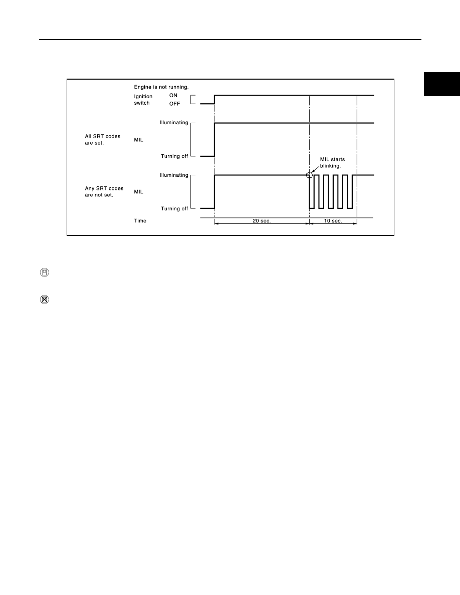
1.
Turn ignition switch ON and wait 20 seconds.
2.
SRT status is indicated as shown below.
• When all SRT codes are set, MIL lights up continuously.
• When any SRT codes are not set, MIL will flash periodically for 10 seconds.
How to Set SRT Code
To set all SRT codes, self-diagnosis for the items indicated above must be performed one or more times. Each
diagnosis may require a long period of actual driving under various conditions.
WITH CONSULT-III
Perform corresponding DTC Confirmation Procedure one by one based on Performance Priority in the table
on "SRT Item".
WITHOUT CONSULT-III
The most efficient driving pattern in which SRT codes can be properly set is explained on the next page. The
driving pattern should be performed one or more times to set all SRT codes.
JMBIA1515GB