Nissan Frontier D40. Manual - part 286
REAR PROPELLER SHAFT
DLN-165
< DISASSEMBLY AND ASSEMBLY >
[3S1330]
C
E
F
G
H
I
J
K
L
M
A
B
DLN
N
O
P
DISASSEMBLY AND ASSEMBLY
REAR PROPELLER SHAFT
Disassembly and Assembly
INFOID:0000000005840685
DISASSEMBLY
Journal
1.
Remove the propeller shaft assembly from the vehicle. Refer to
DLN-163, "Removal and Installation"
.
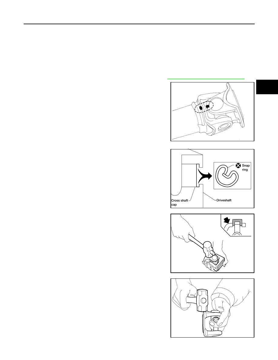
2.
Put matching marks on the rear propeller shaft tube and flange
yoke as shown.
CAUTION:
For matching marks use paint. Never damage the rear pro-
peller shaft or flange yoke.
3.
Remove the snap rings.
4.
Push out and remove the journal bearing by lightly tapping the
yoke with a hammer, taking care not to damage the journal or
yoke hole.
5.
Remove the bearing at the opposite side of above operation.
NOTE:
Put marks on the disassembled parts so that they can be rein-
stalled in their original positions from which they were removed.
SPD128
APD011
SPD732
SPD131