Nissan Frontier D40. Manual - part 270
AIR BREATHER HOSE
DLN-101
< ON-VEHICLE REPAIR >
[TRANSFER: TX15B]
C
E
F
G
H
I
J
K
L
M
A
B
DLN
N
O
P
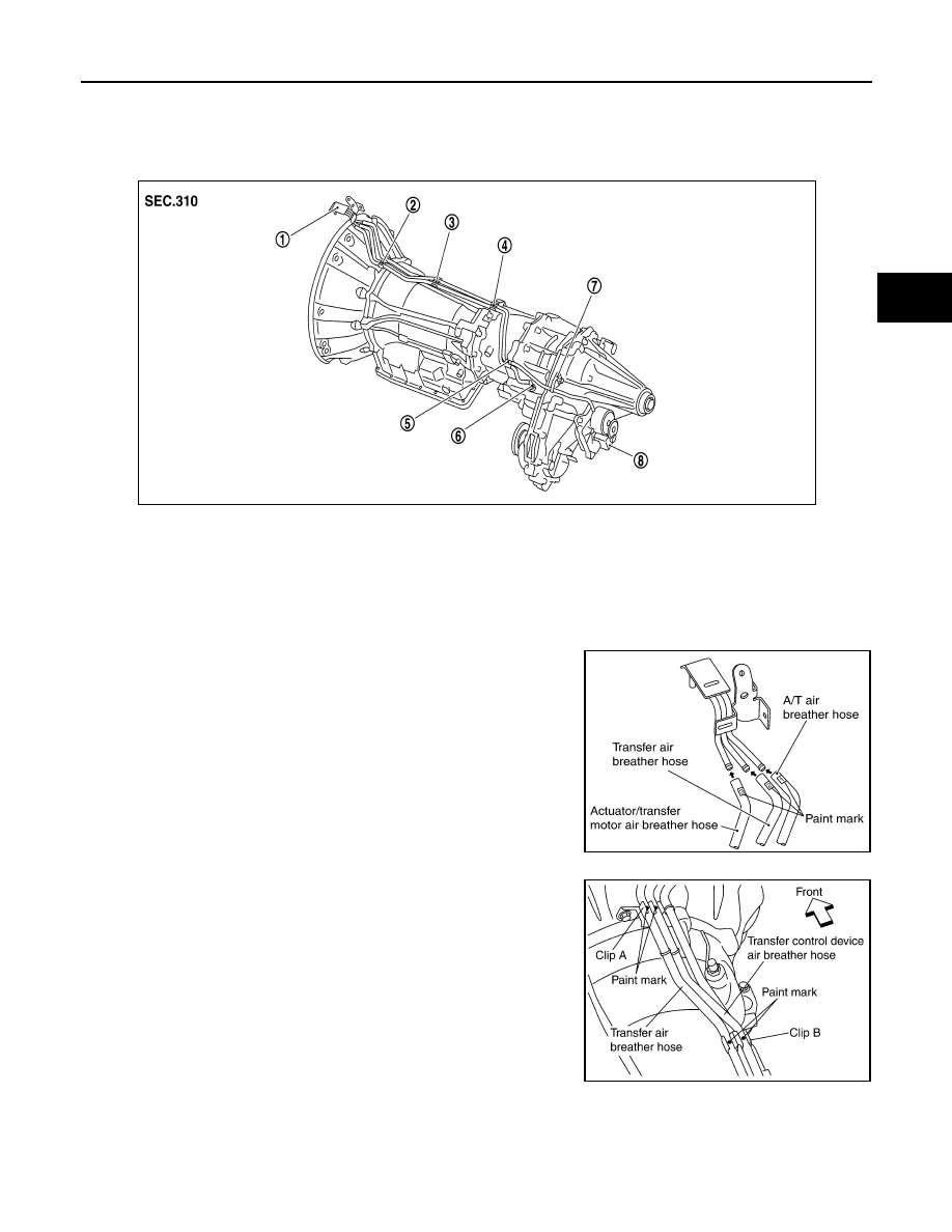
AIR BREATHER HOSE
Removal and Installation
INFOID:0000000005275489
CAUTION:
• Make sure there are no pinched or restricted areas on each air breather hose caused by folding or
bending when installing it.
• Install each air breather hose into the breather tube (metal
connector) until the hose end reaches the end of the curved
section. Set each air breather hose with paint mark facing
upward.
• Install transfer control device air breather hose and transfer
air breather hose on clip A and clip B with the paint mark fac-
ing upward.
1.
Breather tube
2.
Clip A
3.
Clip B
4.
Clip C
5.
Clip D
6.
Breather tube (transfer)
7.
Air breather hose clamp
8.
Transfer control device
SDIA3351E
SDIA3340E
SDIA3353E