Nissan Frontier D40. Manual - part 200
DEF-4
< FUNCTION DIAGNOSIS >
REAR WINDOW DEFOGGER SYSTEM
FUNCTION DIAGNOSIS
REAR WINDOW DEFOGGER SYSTEM
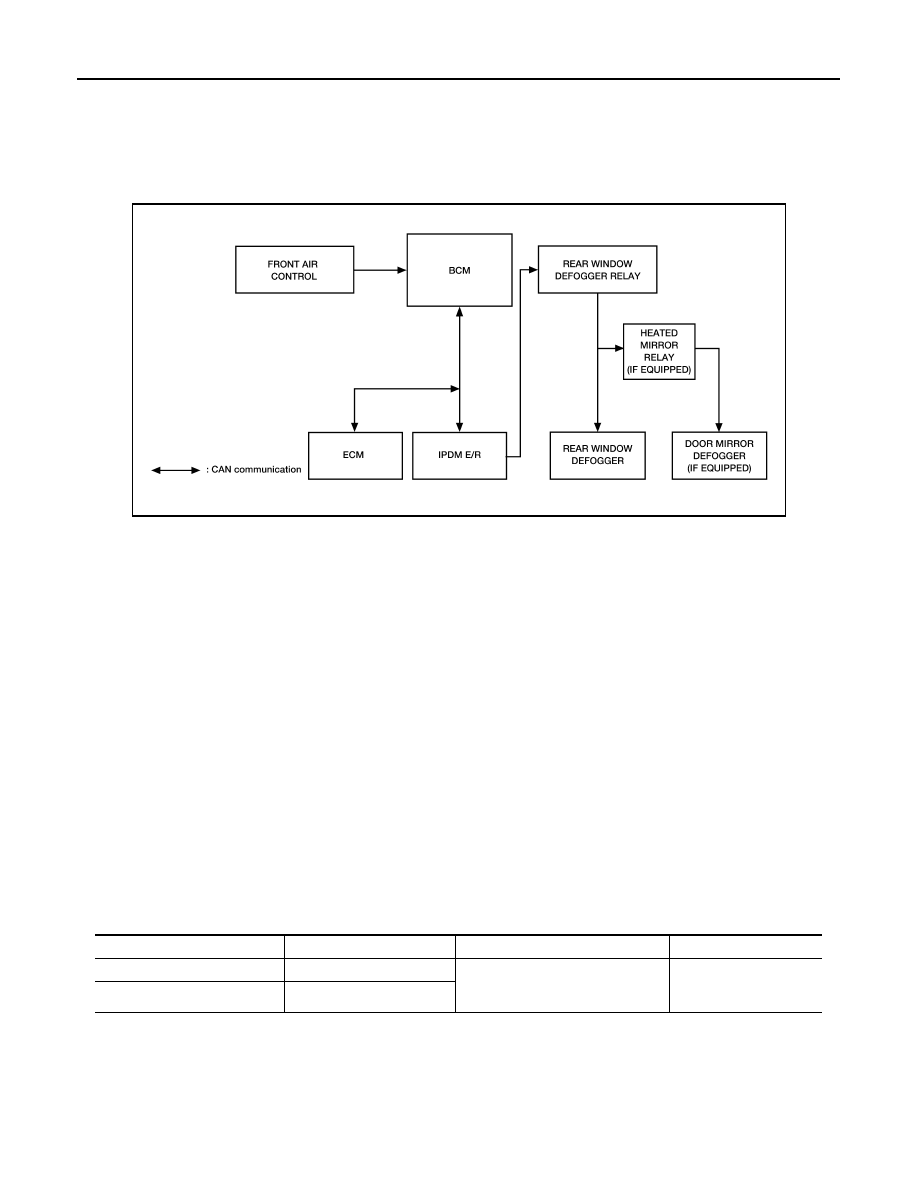
System Diagram
INFOID:0000000005272641
System Description
INFOID:0000000005272642
Operation Description
• When rear window defogger switch is turned ON while ignition switch is ON, the front air control transmits
rear window defogger switch signal to BCM.
• BCM transmits rear window defogger control signal to IPDM E/R via CAN communication when rear window
defogger operates.
• IPDM E/R turns rear window defogger relay and heated mirror relay (if equipped) ON when rear window
defogger switch signal is received.
• Rear window defogger and door mirror defogger (if equipped) are supplied with power and operate when
rear window defogger relay and heated mirror relay (if equipped) turn ON.
• Rear window defogger ON is displayed when signal is received.
Timer function
• BCM turns rear window defogger relay and heated mirror relay (if equipped) ON for approximately 15 min-
utes when rear window defogger switch is turned ON while ignition switch is ON. It makes rear window
defogger and door mirror defogger (if equipped) operate.
• Timer is canceled after pressing rear window defogger switch again during timer operation. Then BCM turns
rear window defogger relay and heated mirror relay (if equipped) OFF. The same reaction also occurs during
timer operation, if the ignition switch is turned OFF.
INPUT/OUTPUT SIGNAL CHART
ALLIA0559GB
Switch
Input signal to BCM
BCM function
Actuator
Rear window defogger switch
Defogger switch signal
Rear window defogger & door mirror
defogger (if equipped) control
Rear window defogger
Door mirror defogger (if
equipped)
Ignition switch
Ignition signal