Nissan Frontier D40. Manual - part 175
CHG
POWER GENERATION VOLTAGE VARIABLE CONTROL SYSTEM OPERATION
INSPECTION
CHG-9
< COMPONENT DIAGNOSIS >
C
D
E
F
G
H
I
J
K
L
B
A
O
P
N
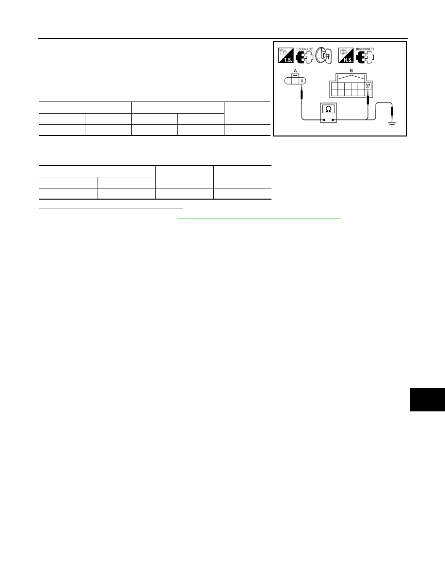
1.
Turn ignition switch OFF.
2.
Disconnect generator connector E205 and IPDM E/R connector
E122.
3.
Check continuity between generator harness connector E205
(A) terminal 4 and IPDM E/R harness connector E122 (B) termi-
nal 37.
4.
Check continuity between generator harness connector E122
(A) terminal 4 and ground.
Are the continuity test results as specified?
YES
>> Replace IPDM E/R. Refer to
PCS-33, "Removal and Installation of IPDM E/R"
.
NO
>> Repair harness or connector between IPDM E/R and generator.
A
B
Continuity
Connector
Terminal
Connector
Terminal
E205
4
E122
37
Yes
A
—
Continuity
Connector
Terminal
E205
4
Ground
No
ALMIA0196ZZ