Nissan Frontier D40. Manual - part 1158


  Index      Nissan     Nissan Frontier D40 (2010 year) - Service and Repair Manual


Search            


Content   ..  1156  1157  1158  1159   ..


Nissan Frontier D40. Manual - part 1158


FRONT WIPER AND WASHER SYSTEM

WW-5

< FUNCTION DIAGNOSIS >

C

D

E

F

G

H

I

J

K

M

A

B

WW

N

O

P

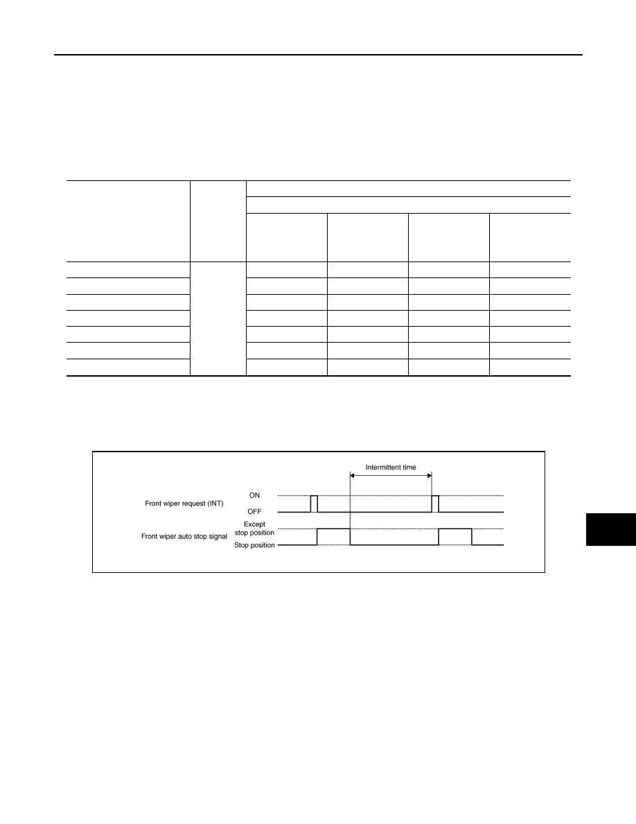
• BCM transmits the front wiper request signal (INT) to IPDM E/R with CAN communication according to the

front wiper INT operation condition and the intermittent operation delay interval judged value.

Front wiper INT operating condition

- Ignition switch ON
- Front wiper switch INT

Intermittent operation delay interval judgment

- BCM calculates the intermittent operation delay interval from the vehicle speed signal received from the

wiper dial position and the combination meter with CAN communication.

• IPDM E/R turns the integrated front wiper relay ON so that the front wiper is operated only once according to

the front wiper request signal (INT).

• BCM detects stop position/except stop position of the front wiper motor according to the front wiper stop

position signal received from IPDM E/R with CAN communication.

• BCM transmits the front wiper request signal (INT) again after the intermittent operation delay interval after

the front wiper motor is stopped.

FRONT WIPER AUTO STOP OPERATION

• BCM stops transmitting the front wiper request signal when the front wiper switch is turned OFF.
• IPDM E/R detects the front wiper auto stop signal from the front wiper motor and detects the front wiper

motor position (stop position/except stop position).

Wiper intermittent dial posi-

tion

Intermittent 

operation 

interval

Intermittent operation delay Interval (s)

Vehicle speed

Vehicle stopped or 

less than 5 km/h 

(3.1 MPH)

5 km/h (3.1 MPH) 

or more or less 

than 35 km/h (21.7 

MPH)

35 km/h (21.7 

MPH) or more or 

less than 65 km/h 

(40.4 MPH)

65 km/h (40.4 

MPH) or more

1

Short

Long

0.8

0.6

0.4

0.24

2

4

3

2

1.2

3

10

7.5

5

3

4

16

12

8

4.8

5

24

18

12

7.2

6

32

24

16

9.6

7

42

31.5

21

12.6

JPLIA0094GB

WW-6

< FUNCTION DIAGNOSIS >

FRONT WIPER AND WASHER SYSTEM

• When the front wiper request signal is stopped, IPDM E/R turns ON the front wiper relay until the front wiper

motor returns to the stop position.

NOTE:
• BCM stops the transmitting of the front wiper request signal when the ignition switch is OFF.
• IPDM E/R turns the front wiper relay OFF when the ignition switch is OFF.

FRONT WIPER OPERATION LINKED WITH WASHER

• BCM transmits the front wiper request signal (LO) to IPDM E/R with CAN communication according to the

washer linked operating condition of the front wiper.

• BCM transmits the front wiper request signal (LO) so that the front wiper operates approximately 3 times

when the front washer switch OFF is detected.

Washer linked operating condition of front wiper

- Ignition switch ON
- Front washer switch ON (0.4 second or more)
• IPDM E/R turns ON the integrated front wiper relay according to the front wiper request signal (LO).
• The front washer motor is grounded through the combination switch with the front washer switch ON.

FRONT WIPER DROP WIPE OPERATION

• BCM controls the front wiper to operate once according to the conditions of front wiper drop wipe operation.

Front wiper drop wipe operating condition

- Ignition switch ON
- Front wiper switch OFF
- Front washer switch OFF
• BCM transmits the front wiper request signal (LO) to IPDM E/R with CAN communication so that the front

wiper operate once three seconds after front wiper operation linked with washer.

• IPDM E/R turns ON the integrated front wiper relay according to the front wiper request signal (LO).

FRONT WIPER FAIL

SAFE OPERATION

• IPDM E/R performs the fail-safe function when the front wiper auto stop circuit is malfunctioning. Refer to

PCS-29, "Fail Safe"

.

JPLIA0095GB

FRONT WIPER AND WASHER SYSTEM

WW-7

< FUNCTION DIAGNOSIS >

C

D

E

F

G

H

I

J

K

M

A

B

WW

N

O

P

Component Parts Location

INFOID:0000000005272682

Component Description

INFOID:0000000005272683

1.

BCM M18, M20 (view with instru-
ment lower panel LH removed)

2.

Front washer motor E105 (view 
with front fender protector RH re-
moved)

3.

Washer fluid reservoir

4.

Front wiper motor E23 (view with 
cowl top removed)

5.

IPDM E/R E121, E122, E124

6.

Combination switch M28

ALLIA0617ZZ

Part

Description

BCM

• Judges each switch status by the combination switch reading function.
• Requests (with CAN communication) the front wiper relay and the front wiper high relay ON to 

IPDM E/R.

IPDM E/R

• Controls the integrated relay according to the request (with CAN communication) from BCM.
• Performs the auto stop control of the front wiper.

Combination switch
(Wiper and washer 
switch)

Refer to 

WW-4, "System Diagram"

.

Combination meter

Transmits the vehicle speed signal to BCM with CAN communication.

WW-8

< FUNCTION DIAGNOSIS >

DIAGNOSIS SYSTEM (BCM)

DIAGNOSIS SYSTEM (BCM)

COMMON ITEM

COMMON ITEM : CONSULT-III Function (BCM - COMMON ITEM)

INFOID:0000000005550178

APPLICATION ITEM

CONSULT-III performs the following functions via CAN communication with BCM.

SYSTEM APPLICATION

BCM can perform the following functions for each system.
NOTE:
It can perform the diagnosis modes except the following for all sub system selection items.

WIPER

WIPER : CONSULT-III Function (BCM - WIPER)

INFOID:0000000005550179

WORK SUPPORT

Diagnosis mode

Function Description

WORK SUPPORT

Changes the setting for each system function.

SELF-DIAG RESULTS

Displays the diagnosis results judged by BCM. Refer to 

BCS-50, "DTC Index"

.

CAN DIAG SUPPORT MNTR

Monitors the reception status of CAN communication viewed from BCM.

DATA MONITOR

The BCM input/output signals are displayed.

ACTIVE TEST

The signals used to activate each device are forcibly supplied from BCM.

ECU IDENTIFICATION

The BCM part number is displayed.

CONFIGURATION

• Enables to read and save the vehicle specification.
• Enables to write the vehicle specification when replacing BCM.

System

Sub system selection item

Diagnosis mode

WORK SUPPORT

DATA MONITOR

ACTIVE TEST

BCM

BCM

×

Door lock

DOOR LOCK

×

×

×

Rear window defogger

REAR DEFOGGER

×

×

Warning chime

BUZZER

×

×

Interior room lamp timer

INT LAMP

×

×

×

Remote keyless entry system

MULTI REMOTE ENT

×

×

×

Exterior lamp

HEAD LAMP

×

×

×

Wiper and washer

WIPER

×

×

×

Turn signal and hazard warning lamps

FLASHER

×

×

Air conditioner

AIR CONDITONER

×

Combination switch

COMB SW

×

Immobilizer

IMMU

×

×

Interior room lamp battery saver

BATTERY SAVER

×

×

×

Vehicle security system

THEFT ALM

×

×

×

RAP (retained accessory power)

RETAINED PWR

×

×

×

Signal buffer system

SIGNAL BUFFER

×

×

TPMS (tire pressure monitoring sys-
tem)

AIR PRESSURE MONITOR 

×

×

×

Panic alarm system

PANIC ALARM

×


Content   ..  1156  1157  1158  1159   ..