Nissan Frontier D40. Manual - part 1093


  Index      Nissan     Nissan Frontier D40 (2010 year) - Service and Repair Manual


Search            


Content   ..  1091  1092  1093  1094   ..


Nissan Frontier D40. Manual - part 1093


TM-270

< ON-VEHICLE MAINTENANCE >

[5AT: RE5R05A]

INSPECTIONS BEFORE TROUBLE DIAGNOSIS
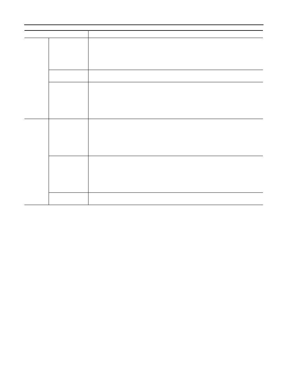
Judgment Possible 

cause

Idle speed

Low for all positions 
(P, R, N, D)

Possible causes include malfunctions in the pressure supply system and low oil pump output.
For example
• Oil  pump  wear
• Pressure regulator valve or plug sticking or spring fatigue
• Oil  strainer 

 oil pump 

 pressure regulator valve passage oil leak

• Engine idle speed too low

Only low for a spe-
cific position

Possible causes include an oil pressure leak in a passage or device related to the position after 
the pressure is distributed by the manual valve.

High

Possible causes include a sensor malfunction or malfunction in the line pressure adjustment func-
tion.
For example
• Accelerator pedal position signal malfunction
• ATF temperature sensor malfunction
• Line pressure solenoid malfunction (sticking in “OFF” state, filter clog, cut line)
• Pressure regulator valve or plug sticking

Stall speed

Oil pressure does 
not rise higher than 
the oil pressure for 
idle.

Possible causes include a sensor malfunction or malfunction in the pressure adjustment function.
For example
• Accelerator pedal position signal malfunction
• TCM breakdown
• Line pressure solenoid malfunction (shorting, sticking in“ ON” state)
• Pressure regulator valve or plug sticking
• Pilot valve sticking or pilot filter clogged

The pressure rises, 
but does not enter 
the standard posi-
tion.

Possible causes include malfunctions in the pressure supply system and malfunction in the pres-
sure adjustment function.
 For example
• Accelerator pedal position signal malfunction
• Line pressure solenoid malfunction (sticking, filter clog)
• Pressure regulator valve or plug sticking
• Pilot valve sticking or pilot filter clogged

Only low for a spe-
cific position

Possible causes include an oil pressure leak in a passage or device related to the position after 
the pressure is distributed by the manual valve.

ROAD TEST

TM-271

< ON-VEHICLE MAINTENANCE >

[5AT: RE5R05A]

C

E

F

G

H

I

J

K

L

M

A

B

TM

N

O

P

ROAD TEST

Description

INFOID:0000000005473958

ROAD TEST 

• The road test inspects overall performance of the A/T and analyzes possible malfunction causes.
• The road test is carried out in the following three stages.

1.

Check before engine is started. Refer to 

TM-271

2.

Check at idle. Refer to 

TM-271

.

3.

Cruise test
• Inspect all the items from Part 1 to Part 3. Refer to 

TM-272

TM-274

TM-274

• Before beginning the road test, check the test procedure and inspection items.
• Test all inspection items until the symptom is uncovered. Diagnose NG items when all road tests are com-

plete.

Check Before Engine Is Started

INFOID:0000000005274197

1.

CHECK O/D OFF INDICATOR LAMP

1.

Park vehicle on level surface.

2.

Move selector lever to “P” position.

3.

Turn ignition switch to “OFF” position and wait at least 10 seconds.

4.

Turn ignition switch to “ON” position. (Do not start engine.)

Does O/D OFF indicator lamp light up for about 2 seconds?

YES

>> 1.

Turn ignition switch “OFF”.

2.

Perform self-diagnostics and record all NG items on the 

TM-125, "Diagnostic Work Sheet"

.

Refer to 

TM-151, "CONSULT-III Function (TRANSMISSION)"

TM-156, "Diagnosis Procedure

without CONSULT-III"

.

3.

Go to 

TM-271, "Check at Idle"

.

NO

>> Stop the test and go to 

TM-235, "Symptom Chart"

.

Check at Idle

INFOID:0000000005274198

1.

CHECK STARTING THE ENGINE

1.

Park vehicle on level surface.

2.

Move selector lever to “P” or “N” position.

3.

Turn ignition switch to “OFF” position.

4.

Turn ignition switch to “START” position.

Does the engine start?

YES

>> GO TO 2.

NO

>> Stop the road test and go to 

TM-235, "Symptom Chart"

.

2.

CHECK STARTING THE ENGINE

1.

Turn ignition switch to “ON” position.

2.

Move selector lever in “D”, “3”, “2”, “1” or “R” position.

3.

Turn ignition switch to “START” position.

Does the engine start in either position?

YES

>> Stop the road test and go to 

TM-235, "Symptom Chart"

.

NO

>> GO TO 3.

3.

CHECK “P” POSITION FUNCTIONS

1.

Move selector lever to “P” position.

2.

Turn ignition switch to “OFF” position.

3.

Release the parking brake.

4.

Push the vehicle forward or backward.

5.

Engage the parking brake.

TM-272

< ON-VEHICLE MAINTENANCE >

[5AT: RE5R05A]

ROAD TEST

When you push the vehicle with disengaging the parking brake, does it move?

YES

>> Record the malfunction, GO TO 4.

NO

>> GO TO 4. 

4.

CHECK “N” POSITION FUNCTIONS

1.

Start the engine.

2.

Move selector lever to “N” position.

3.

Release the parking brake.

Does vehicle move forward or backward?

YES

>> Record the malfunction, GO TO 5. 

NO

>> GO TO 5.

5.

CHECK SHIFT SHOCK

1.

Engage the brake.

2.

Move selector lever to “D” position.

When the transmission is shifted from “N” to “D”, is there an excessive shock?

YES

>> Record the malfunction, GO TO 6.

NO

>> GO TO 6.

6.

CHECK “R” POSITION FUNCTIONS

1.

Engage the brake.

2.

Move selector lever to “R” position.

3.

Release the brake for 4 to 5 seconds.

Does the vehicle creep backward?

YES

>> GO TO 7.

NO

>> Record the malfunction, GO TO 7.

7.

CHECK “D” POSITION FUNCTIONS 

Inspect whether the vehicle creep forward when the transmission is put into the “D” position.

Does the vehicle creep forward in the “D” positions?

YES

>> Go to 

TM-272, "Cruise Test - Part 1"

.

NO

>> Record the malfunction and go to 

TM-272, "Cruise Test - Part 1"

Cruise Test - Part 1

INFOID:0000000005274199

1.

CHECK STARTING OUT FROM D1

1.

Drive the vehicle for about 10 minutes to warm up the engine oil and ATF.
Appropriate temperature for the ATF: 50 - 80

°

C (122 - 176

°

F)

2.

Park the vehicle on a level surface.

3.

Move selector lever to “P” position.

4.

Start the engine.

5.

Set overdrive control switch to ON position (without manual mode).

6.

Move selector lever to “D” position.

7.

Press the accelerator pedal about half way down to accelerate the vehicle.

With CONSULT-III

Read off the gear positions.

Starts from D1?

YES

>> GO TO 2.

NO

>> Record the malfunction,GO TO 2.

2.

CHECK SHIFT-UP D1 

 D2

Press down the accelerator pedal about half way and inspect if the vehicle shifts up (D1 

 D2) at the appropri-

ate speed.
• Refer to 

TM-381, "Vehicle Speed at Which Gear Shifting Occurs"

.

With CONSULT-III

Read the gear position, throttle degree of opening, and vehicle speed.

Does the A/T shift-up D1 

 D2 at the correct speed?

ROAD TEST

TM-273

< ON-VEHICLE MAINTENANCE >

[5AT: RE5R05A]

C

E

F

G

H

I

J

K

L

M

A

B

TM

N

O

P

YES

>> GO TO 3.

NO

>> Record the malfunction,GO TO 3.

3.

CHECK SHIFT-UP D2 

 D3

Press down the accelerator pedal about half way and inspect if the vehicle shifts up (D2 

 D3) at the appropri-

ate speed.
• Refer to 

TM-381, "Vehicle Speed at Which Gear Shifting Occurs"

.

With CONSULT-III

Read the gear position, throttle degree of opening, and vehicle speed.

Does the A/T shift-up D2 

 D3 at the correct speed?

YES

>> GO TO 4.

NO

>> Record the malfunction, GO TO 4.

4.

CHECK SHIFT-UP D3 

 D4

Press down the accelerator pedal about half way and inspect if the vehicle shifts up (D3 

 D4) at the appropri-

ate speed.
• Refer to 

TM-381, "Vehicle Speed at Which Gear Shifting Occurs"

.

With CONSULT-III

Read the gear position, throttle degree of opening, and vehicle speed.

Does the A/T shift-up D3 

 D4 at the correct speed?

YES

>> GO TO 5.

NO

>> Record the malfunction, GO TO 5.

5.

CHECK SHIFT-UP D4 

 D5

Press down the accelerator pedal about half way and inspect if the vehicle shifts up (D4 

 D5) at the appropri-

ate speed.
• Refer to 

TM-381, "Vehicle Speed at Which Gear Shifting Occurs"

.

With CONSULT-III

Read the gear position, throttle degree of opening, and vehicle speed.

Does the A/T shift-up D4 

 D5 at the correct speed?

YES

>> GO TO 6.

NO

>> Record the malfunction, GO TO 6.

6.

CHECK LOCK-UP 

When releasing accelerator pedal from D5 (closed throttle position signal: OFF), check lock-up from D5 to L/U.
• Refer to 

TM-381, "Vehicle Speed at Which Gear Shifting Occurs"

.

With CONSULT-III

Select “TCC SOLENOID” with the “MAIN SIGNAL” mode for “TRANSMISSION”.

Does it lock-up? 

YES

>> GO TO 7.

NO

>> Record the malfunction, GO TO 7.

7.

CHECK LOCK-UP HOLD

Check hold lock-up.

With CONSULT-III

Select “TCC SOLENOID” with the “MAIN SIGNAL” mode for “TRANSMISSION”.

Does it maintain lock-up status?

YES

>> GO TO 8.

NO

>> Record the malfunction, GO TO 8.

8.

CHECK LOCK-UP RELEASE

Check lock-up cancellation by depressing brake pedal lightly to decelerate.

With CONSULT-III

Select “TCC SOLENOID” with the “MAIN SIGNAL” mode for “TRANSMISSION”.
Does lock-up cancel?

YES

>> GO TO 9.


Content   ..  1091  1092  1093  1094   ..