Nissan Frontier D40. Manual - part 1065


  Index      Nissan     Nissan Frontier D40 (2010 year) - Service and Repair Manual


Search            


Content   ..  1063  1064  1065  1066   ..


Nissan Frontier D40. Manual - part 1065


TM-158

< FUNCTION DIAGNOSIS >

[5AT: RE5R05A]

DIAGNOSIS SYSTEM (TCM)

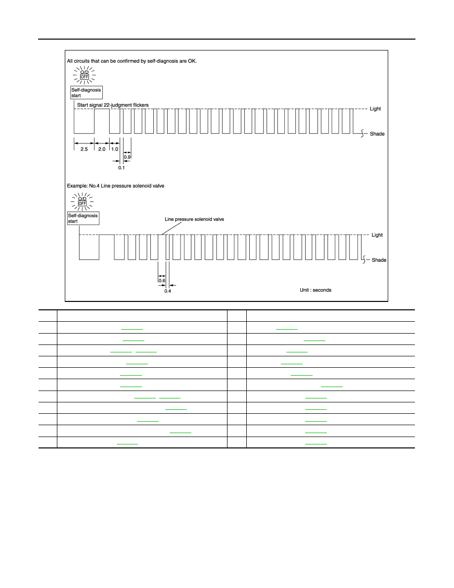
If there is a malfunction, the lamp lights up for the time corresponding to the suspect circuit.

Erase Self-diagnosis

• In order to make it easier to find the cause of hard-to-duplicate malfunctions, malfunction information is

stored into the control unit as necessary during use by the user. This memory is not erased no matter how
many times the ignition switch is turned ON and OFF. 

• However, this information is erased by turning ignition switch OFF after executing self-diagnostics or by

erasing the memory using the CONSULT-III.

JSDIA1433GB

No.

Malfunctioning item

No.

Malfunctioning item

1

Output speed sensor 

TM-167

12

Interloc

TM-194

2

Direct clutch solenoid 

TM-202

13

1st engine brakin

TM-196

3

Torque converter 

TM-182

TM-184

14

Starter relay 

TM-160

4

Line pressure solenoid 

TM-186

15

TP sensor 

TM-188

5

Input clutch solenoid 

TM-198

16

Engine speed 

TM-170

6

Front brake solenoi

TM-200

17

CAN communication line 

TM-159

7

Low coast brake solenoid 

TM-206

TM-208

18

1GR incorrect ratio 

TM-172

8

High and low reverse clutch solenoid 

TM-204

19

2GR incorrect ratio 

TM-174

9

Transmission range switch 

TM-163

20

3GR incorrect ratio 

TM-176

10

Transmission fluid temperature sensor 

TM-190

21

4GR incorrect ratio 

TM-178

11

Input speed sensor 

TM-165

22

5GR incorrect ratio 

TM-180

U1000 CAN COMM CIRCUIT

TM-159

< COMPONENT DIAGNOSIS >

[5AT: RE5R05A]

C

E

F

G

H

I

J

K

L

M

A

B

TM

N

O

P

COMPONENT DIAGNOSIS

U1000 CAN COMM CIRCUIT

Description

INFOID:0000000005273998

CAN (Controller Area Network) is a serial communication line for real time application. It is an on-vehicle mul-
tiplex communication line with high data communication speed and excellent malfunction detection ability.
Many electronic control units are equipped onto a vehicle, and each control unit shares information and links
with other control units during operation (not independent). In CAN communication, control units are con-
nected with 2 communication lines (CAN H line, CAN L line) allowing a high rate of information transmission
with less wiring. Each control unit transmits/receives data but selectively reads required data only.

On Board Diagnosis Logic

INFOID:0000000005273999

• This is an OBD-II self-diagnostic item.
• Diagnostic trouble code “U1000” with CONSULT-III or 17th judgment flicker without CONSULT-III is detected

when TCM cannot communicate to other control units.

Possible Cause

INFOID:0000000005274000

Harness or connectors
(CAN communication line is open or shorted.)

DTC Confirmation Procedure

INFOID:0000000005274001

NOTE:
If “DTC Confirmation Procedure” has been previously performed, always turn ignition switch “OFF”
and wait at least 10 seconds before performing the next test.
After the repair, perform the following procedure to confirm the malfunction is eliminated.

 WITH CONSULT-III

1.

Turn ignition switch “ON”. (Do not start engine.)

2.

Select “DATA MONITOR” mode for “TRANSMISSION” with CONSULT-III.

3.

Start engine and wait for at least 6 seconds.

4.

If DTC is detected, go to 

TM-159, "Diagnosis Procedure"

.

 WITH GST

Follow the procedure “WITH CONSULT-III”.

Diagnosis Procedure

INFOID:0000000005274002

1.

CHECK CAN COMMUNICATION CIRCUIT

With CONSULT-III

1.

Turn ignition switch “ON” and start engine.

2.

Select “SELF-DIAG RESULTS” mode for “TRANSMISSION” with CONSULT-III.

Is any malfunction of the “U1000” indicated?

YES

>> Go to LAN section. Refer to 

LAN-14, "Trouble Diagnosis Flow Chart"

.

NO

>> INSPECTION END

TM-160

< COMPONENT DIAGNOSIS >

[5AT: RE5R05A]

P0615 STARTER RELAY

P0615 STARTER RELAY

Description

INFOID:0000000005274003

TCM prohibits cranking other than at “P” or “N” position.

CONSULT-III Reference Value in Data Monitor Mode

INFOID:0000000005274004

On Board Diagnosis Logic

INFOID:0000000005274005

• This is not an OBD-II self-diagnostic item. 
• Diagnostic trouble code “P0615” with CONSULT-III or 14th judgment flicker without CONSULT-III is detected

when starter relay is switched “ON” other than at “P” or “N” position. (Or when switched “OFF” at “P” or “N”
position).

Possible Cause

INFOID:0000000005274006

• Harness or connectors

(The starter relay and TCM circuit is open or shorted.)

• Starter relay

DTC Confirmation Procedure

INFOID:0000000005274007

NOTE:
If “DTC Confirmation Procedure” has been previously performed, always turn ignition switch “OFF”
and wait at least 10 seconds before performing the next test.
After the repair, perform the following procedure to confirm the malfunction is eliminated.

 WITH CONSULT-III

1.

Shift selector lever to “P” or “N” position.

2.

Turn ignition switch ON and wait for at least 2 seconds.

3.

Select “SELF-DIAG RESULTS” mode for “TRANSMISSION” with CONSULT-III.

4.

If DTC is detected, go to 

TM-160, "Diagnosis Procedure"

.

Diagnosis Procedure

INFOID:0000000005274008

1.

CHECK STARTER RELAY

With CONSULT-III

1.

Turn ignition switch ON. (Do not start engine.)

2.

Select “SELECTION FROM MENU” in “DATA MONITOR” mode for "TRANSMISSION" with CONSULT-III
and check monitor “STARTER RELAY” ON/OFF.

Without CONSULT-III

1.

Turn ignition switch ON. (Do not start engine.)

2.

Check voltage between the IPDM E/R connector and ground.

OK or NG

OK

>> GO TO 5.

NG

>> GO TO 2.

Item name

Condition 

Display value

STARTER RELAY

Selector lever in “N”, “P” positions.

ON

Selector lever in other position.

OFF

Item

Connector

Terminal

Shift position

Voltage (Ap-

prox.) 

Starter relay

E122

48

Ground

“N” and “P”

Battery voltage

“R” and “D”

0V

LCIA0320E

P0615 STARTER RELAY

TM-161

< COMPONENT DIAGNOSIS >

[5AT: RE5R05A]

C

E

F

G

H

I

J

K

L

M

A

B

TM

N

O

P

2.

 CHECK HARNESS BETWEEN A/T ASSEMBLY HARNESS CONNECTOR AND IPDM E/R CONNECTOR

1.

Turn ignition switch OFF.

2.

Disconnect A/T assembly harness connector and IPDM E/R connector.

3.

Check continuity between A/T assembly harness connector and
IPDM E/R connector.

4.

If OK, check harness for short to ground and short to power.

5.

Reinstall any part removed.

OK or NG

OK

>> GO TO 3.

NG

>> Repair open circuit or short to ground or short to power in harness or connectors.

3.

CHECK TERMINAL CORD ASSEMBLY

1.

Remove control valve with TCM. Refer to 

TM-280, "Removal and Installation"

.

2.

Disconnect A/T assembly harness connector and TCM connector.

3.

Check continuity between A/T assembly harness connector ter-
minal and TCM connector terminal.

4.

If OK, check harness for short to ground and short to power.

5.

Reinstall any part removed.

OK or NG

OK

>> GO TO 4.

NG

>> Replace open circuit or short to ground and short to power in harness or connectors.

4.

DETECT MALFUNCTIONING ITEM

Check the following.
• Starter relay, Refer to 

STR-8

.

• IPDM E/R, Refer to 

PCS-8

.

OK or NG

OK

>> Replace the control valve with TCM. Refer to 

TM-280, "Removal and Installation"

.

NG

>> Repair or replace damaged parts.

5.

CHECK DTC

Perfor

TM-160, "DTC Confirmation Procedure"

.

OK or NG

OK

>> INSPECTION END

NG

>> GO TO 2.

Item

 Connector

Terminal

Continuity

A/T assembly harness 
connector

F9

9

Yes

IPDM E/R connector

E122

48

SCIA6254E

Item

 Connector

Terminal

Continuity

A/T assembly harness 
connector

F9

9

Yes

TCM connector 

F502

8

SCIA5440E


Content   ..  1063  1064  1065  1066   ..