Content .. 1046 1047 1048 1049 ..
Nissan Frontier D40. Manual - part 1048
TM-90
< DISASSEMBLY AND ASSEMBLY >
[6MT: FS6R31A]
SHIFT CONTROL COMPONENTS
SHIFT CONTROL COMPONENTS
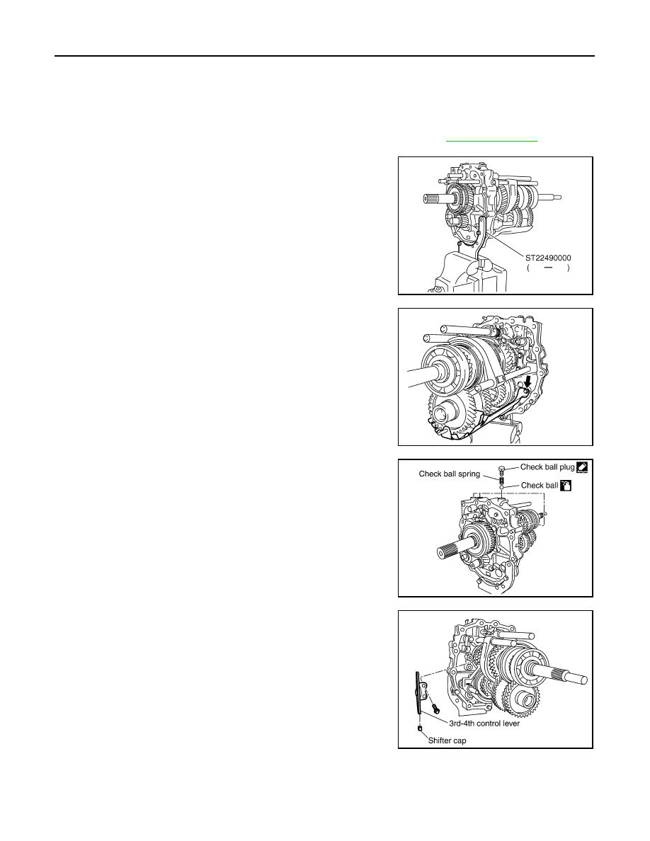
Disassembly
INFOID:0000000005589599
SHIFT CONTROL COMPONENTS
1.
Remove rear extension (or OD gear case) and transmission case. Refer to
2.
Install Tool to adapter plate, and then position in a vise.
CAUTION:
Do not directly secure mating surface of adapter plate in a
vise.
3.
Remove baffle plate bolts, and then remove baffle plate from
adapter plate.
4.
Remove check ball plugs, check ball springs and check balls
from adapter plate.
5.
Remove 3rd-4th control lever bolts, and then remove 3rd-4th
control lever and shifter cap from adapter plate.
Tool number
: ST22490000 (
—
)
PCIB1230E
PCIB1325E
PCIB1231E
PCIB1232E