Content .. 1018 1019 1020 1021 ..
Nissan Frontier D40. Manual - part 1020
B TERMINAL CIRCUIT
STR-13
< COMPONENT DIAGNOSIS >
C
D
E
F
G
H
I
J
K
L
M
A
STR
N
P
O
COMPONENT DIAGNOSIS
B TERMINAL CIRCUIT
Description
INFOID:0000000005276063
Terminal "2" (B) is constantly supplied with battery power.
Diagnosis Procedure
INFOID:0000000005276064
Regarding Wiring Diagram information, refer to
STR-18, "Wiring Diagram - VQ40DE - With Clutch Interlock
STR-24, "Wiring Diagram - VQ40DE - Without Clutch Interlock Cancel Switch"
.
CAUTION:
Perform diagnosis under the condition that the engine cannot start by the following procedure.
1.
Remove fuel pump fuse.
2.
Crank or start the engine (where possible) until the fuel pressure is depleted.
1.
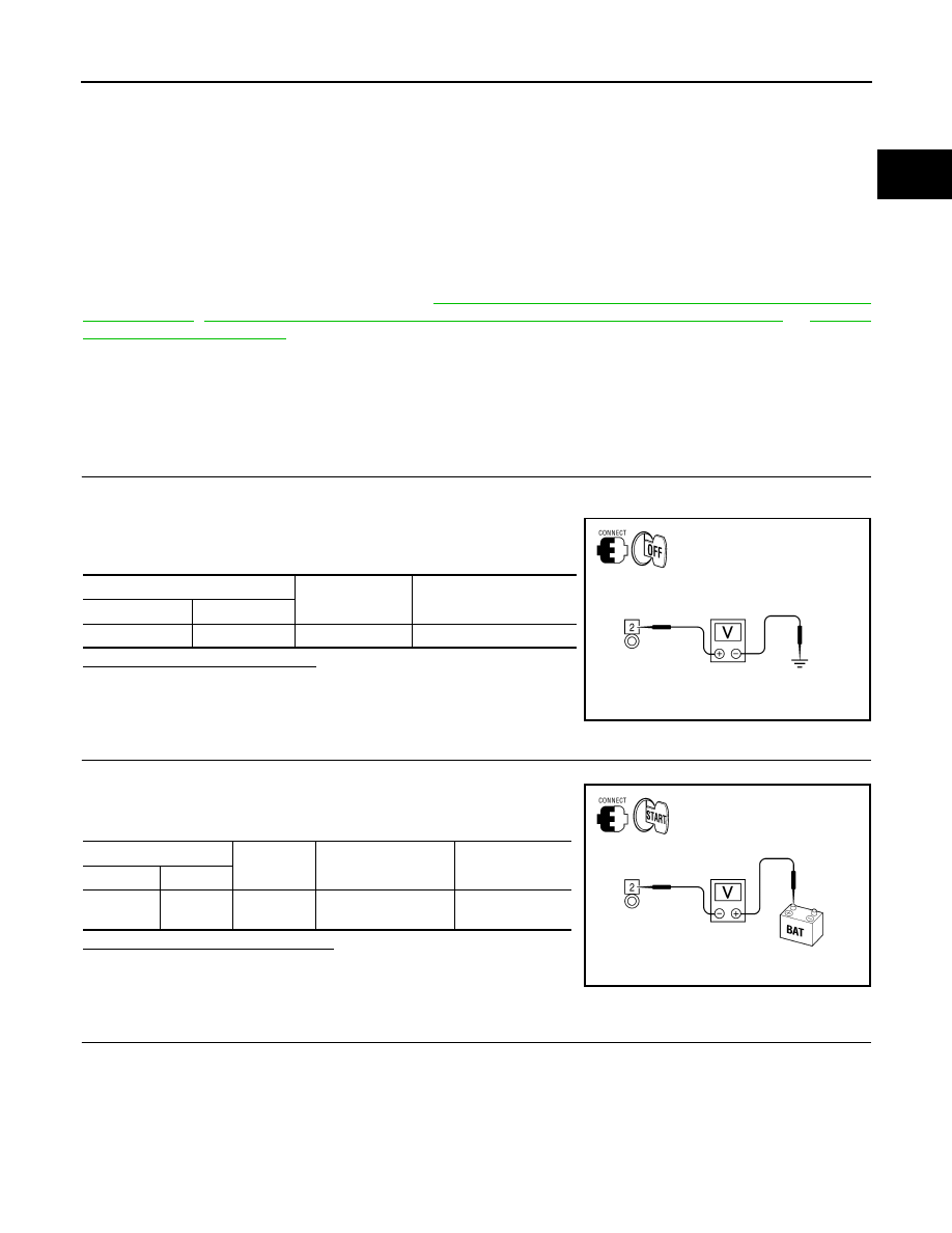
CHECK TERMINAL 2 POWER SUPPLY VOLTAGE
1.
Turn ignition switch OFF.
2.
Make sure that starter motor connector E210 terminal 2 connection is clean and tight.
3.
Check voltage between starter motor connector E210 terminal 2
and ground.
Is there battery voltage present?
YES
>> GO TO 2
NO
>> Check harness between battery and starter motor for
open circuit.
2.
CHECK BATTERY CABLE (VOLTAGE DROP TEST)
1.
Shift the transmission into park or neutral.
2.
Check voltage between battery positive terminal and starter
motor connector E210 terminal 2 while cranking the engine.
Is the voltage drop less than 0.2V?
YES
>> GO TO 3
NO
>> Check harness between the battery and the starter
motor for high resistance.
3.
CHECK GROUND CIRCUIT STATUS (VOLTAGE DROP TEST)
(+)
(-)
Voltage
Connector
Terminal
E210
2
Ground
Battery voltage
AWBIA0122GB
(-)
(+)
Condition
Voltage
Connector
Terminal
E210
2
Battery (+)
terminal
While cranking the
engine
Less than 0.2V
AWBIA0123GB