Nissan Frontier D40. Manual - part 75


  Index      Nissan     Nissan Frontier D40 (2010 year) - Service and Repair Manual


Search            


Content   ..  73  74  75  76   ..


Nissan Frontier D40. Manual - part 75


BR-56

< DISASSEMBLY AND ASSEMBLY >

REAR DISC BRAKE

2.

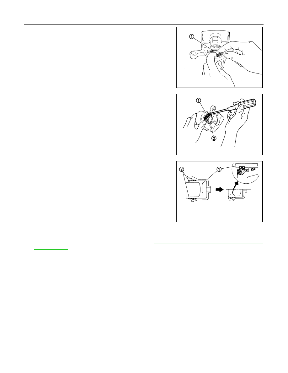
Apply rubber grease to the new piston seal (1) and insert the
new piston seal (1) into the groove on the cylinder body.

CAUTION:

Do not reuse piston seal.

3.

Apply rubber grease to the new piston boot (1). Cover the piston
end (2) with the piston boot (1), and then install the cylinder side
lip on the piston boot (1) securely into the groove on the cylinder
body.

CAUTION:

• Do not reuse piston boot.
• Press pistons in evenly and vary the pressing points to

prevent the cylinder inner wall from being damaged.

4.

Install the piston (1) into the cylinder body and insert the piston
boot (2) side lip into the piston groove as shown. 

CAUTION:

Press pistons in evenly and vary the pressing points to pre-
vent the cylinder inner wall from being damaged.

5.

Apply rubber grease to the sliding pin boots, then install sliding pins and sliding pin boots on the torque
member.

6.

Install the caliper body on the torque member. Refer to 

BR-46, "Removal and Installation of Brake Caliper

and Disc Rotor"

.

JPFIA0039ZZ

JPFIA0040ZZ

JPFIA0041ZZ

SERVICE DATA AND SPECIFICATIONS (SDS)

BR-57

< SERVICE DATA AND SPECIFICATIONS (SDS) 

C

D

E

G

H

I

J

K

L

M

A

B

BR

N

O

P

SERVICE DATA AND SPECIFICATIONS (SDS)

SERVICE DATA AND SPECIFICATIONS (SDS)

General Specification

INFOID:0000000005272499

Unit: mm (in)

Brake Pedal

INFOID:0000000005272500

Unit: mm (in)

Engine Type

QR25DE

VQ40DE

Front brake

Brake model

CLZ33VA

Rotor outer diameter 

×

 thickness

283 

×

 28 (11.142 

×

 1.102)

296 

×

 28 (11.654 

×

 1.102)

Pad Length × width × thickness

140 × 49 × 10 (5.51 × 1.93 × 0.39)

Cylinder bore diameter (each)

46.4 (1.83)

Rear brake 

Brake model

CLZ14VA

Rotor outer diameter 

×

 thickness

286 

×

 18 (11.260 

×

 0.709)

Pad length 

×

 width 

×

 thickness

87.6 

×

 35.5 

×

 11.0 (3.449 

×

 1.398 

×

 0.433)

Cylinder bore diameter

38.1 (1.50)

Control valve

Valve model

Electric brake force distribution

Brake booster

Booster model

C215T

Diaphragm diameter

215 (8.465)

Recommended brake fluid

Refer to 

MA-16, "For North America: Fluids and Lubricants"

.

Pedal free height (H)

M/T

174.7 (6.88)

A/T

182.1 (7.17)

Pedal full stroke (S)

153 (6.02)

Clearance between pedal stopper and threaded end of stop lamp switch and ASCD switch (C

1

) or (C

2

)

0.74 - 1.96 (0.029 - 0.077)

AWFIA0557ZZ

BR-58

< SERVICE DATA AND SPECIFICATIONS (SDS) 

SERVICE DATA AND SPECIFICATIONS (SDS)

Brake Booster

INFOID:0000000005272501

Unit: mm (in)

Check Valve

INFOID:0000000005272502

Front Disc Brake

INFOID:0000000005272503

Unit: mm (in)

Rear Disc Brake

INFOID:0000000005272504

Unit: mm (in)

Input rod (2) with lock nut (1) length (A) standard dimension

149 

±

 0.5 (5.87 

±

 0.02)

JPFIA0238ZZ

Vacuum leakage 
[at vacuum of -66.7 kPa(-500 mmHg, -19.69 inHg)]

Within 1.3 kPa (10 mmHg, 0.39 inHg) of vacuum for 15 seconds

Engine type

QR25DE / VQ40DE

Brake model

CLZ33VA

Brake pad

Standard thickness (new)

10.0 (0.394)

Repair limit thickness

2.0 (0.079)

Disc rotor

Standard thickness (new)

28.0 (1.102)

Repair limit thickness

26.0 (1.024)

Maximum uneven wear (measured at 8 positions)

0.015 (0.0006) 

Runout limit (with it attached to the vehicle)

0.05 (0.0020) 

Engine type

QR25DE / VQ40DE

Brake model

CLZ14VA

Brake pad

Standard thickness (new)

11.0 (0.433)

Repair limit thickness

2.0 (0.079)

Disc rotor

Standard thickness (new)

18.0 (0.709)

Repair limit thickness

16.0 (0.630)

Maximum uneven wear (measured at 8 positions)

0.015 (0.0006) 

Runout limit (with it attached to the vehicle)

0.05 (0.0020) 

BRC-1

BRAKES

C

D

E

G

H

I

J

K

L

M

SECTION 

BRC

A

B

BRC

N

O

P

CONTENTS

BRAKE CONTROL SYSTEM

TYPE 1

BASIC INSPECTION  ....................................

9

APPLICATION NOTICE  ......................................

9

Application Notice  .....................................................

9

DIAGNOSIS AND REPAIR WORKFLOW  .........

10

Work Flow  ...............................................................

10

Diagnostic Work Sheet ............................................

12

FUNCTION DIAGNOSIS ..............................

13

APPLICATION NOTICE  .....................................

13

Application Notice  ...................................................

13

ABS ....................................................................

14

System Diagram ......................................................

14

System Description  .................................................

15

Component Parts Location ......................................

16

Component Description ...........................................

17

EBD ....................................................................

18

System Diagram ......................................................

18

System Description  .................................................

18

Component Parts Location ......................................

19

Component Description ...........................................

20

DIAGNOSIS SYSTEM [ABS ACTUATOR 
AND ELECTRIC UNIT (CONTROL UNIT)]  ........

21

CONSULT-III Function (ABS)  .................................

21

COMPONENT DIAGNOSIS  .........................

24

APPLICATION NOTICE  .....................................

24

Application Notice  ...................................................

24

C1101, C1102, C1103, C1104 WHEEL SEN-
SOR-1 .................................................................

25

Description ..............................................................

25

DTC Logic  ...............................................................

25

Diagnosis Procedure ...............................................

25

Component Inspection  ............................................

27

C1105, C1106, C1107, C1108 WHEEL SEN-
SOR-2 ................................................................

28

Description ...............................................................

28

DTC Logic ................................................................

28

Diagnosis Procedure  ...............................................

28

Component Inspection .............................................

30

C1109 POWER AND GROUND SYSTEM  ........

31

Description ...............................................................

31

DTC Logic ................................................................

31

Diagnosis Procedure  ...............................................

31

C1110, C1113, C1170 ABS ACTUATOR AND 
ELECTRIC UNIT (CONTROL UNIT) .................

33

DTC Logic ................................................................

33

Diagnosis Procedure  ...............................................

33

C1111 ABS MOTOR, MOTOR RELAY SYS-
TEM ...................................................................

34

Description ...............................................................

34

DTC Logic ................................................................

34

Diagnosis Procedure  ...............................................

34

Component Inspection .............................................

35

C1115 WHEEL SENSOR  ..................................

36

Description ...............................................................

36

DTC Logic ................................................................

36

Diagnosis Procedure  ...............................................

36

Component Inspection .............................................

37

C1120, C1122, C1190 IN ABS SOL  .................

39

Description ...............................................................

39

DTC Logic ................................................................

39

Diagnosis Procedure  ...............................................

39

Component Inspection .............................................

40

C1121, C1123, C1191 OUT ABS SOL  .............

41

Description ...............................................................

41

DTC Logic ................................................................

41

Diagnosis Procedure  ...............................................

41

Component Inspection .............................................

42


Content   ..  73  74  75  76   ..