Nissan Frontier D40. Manual - part 65
BR-16
< BASIC INSPECTION >
BRAKE TUBE AND HOSE
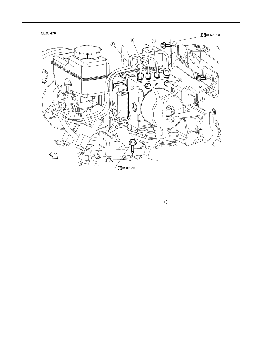
Type 2
ALFIA0146ZZ
1.
From the master cylinder secondary side
18.2 N·m (1.9 kg-m, 13 ft-lb)
2.
To rear right disc brake
13.0 N·m (1.3 kg-m, 10 ft-lb)
3.
To rear left disc brake
13.0 N·m (1.3 kg-m, 10 ft-lb)
4.
To front right disc brake
13.0 N·m (1.3 kg-m, 10 ft-lb)
5.
To front left disc brake
13.0 N·m (1.3 kg-m, 10 ft-lb)
6.
From the master cylinder primary side
18.2 N·m (1.9 kg-m, 13 ft-lb)
7.
ABS actuator and electric unit (control unit) 8.
Harness connector
Front