Nissan Frontier D40. Manual - part 13


  Index      Nissan     Nissan Frontier D40 (2010 year) - Service and Repair Manual


Search            


Content   ..  11  12  13  14   ..


Nissan Frontier D40. Manual - part 13


AV-44

< COMPONENT DIAGNOSIS >

[PREMIUM AUDIO (KING CAB)]

POWER SUPPLY AND GROUND CIRCUIT

Are the fuses OK?

YES

>> GO TO 2

NO

>> If fuse is blown, be sure to eliminate cause of malfunction before installing new fuse.

2.

POWER SUPPLY CIRCUIT CHECK
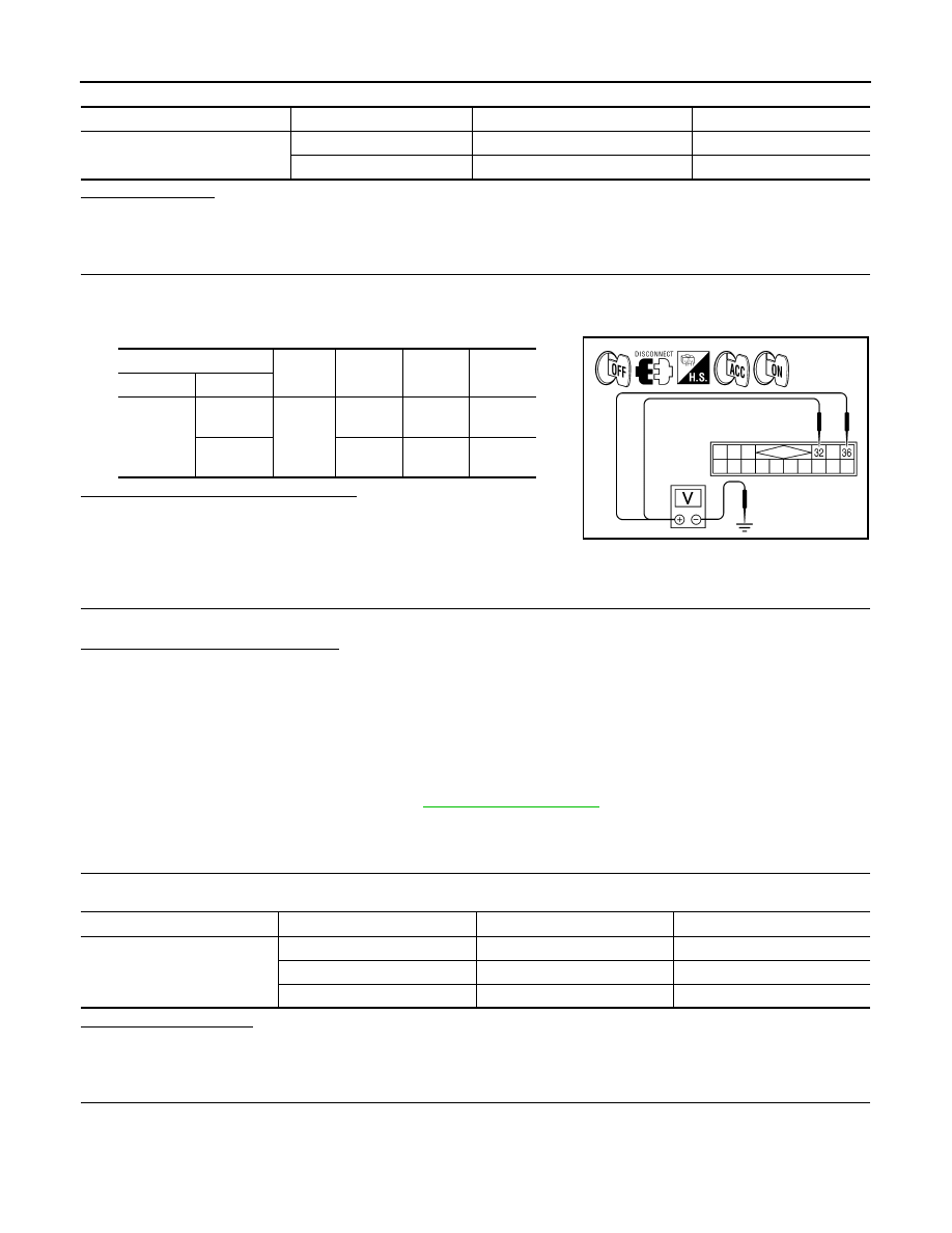
1.

Turn ignition switch OFF.

2.

Disconnect satellite radio tuner (factory installed) connector M41. 

3.

Check voltage between the satellite radio tuner (factory installed) and ground.

Are the voltage readings as specified?

YES

>> GO TO 3

NO

>> • Check connector housings for disconnected or loose

terminals.

• Repair harness or connector.

3.

GROUND CIRCUIT CHECK

Inspect satellite radio tuner (factory installed) case ground.

Does case ground pass inspection?

YES

>> Inspection End.

NO

>> Repair satellite radio tuner (factory installed) case ground.

BLUETOOTH CONTROL UNIT

BLUETOOTH CONTROL UNIT : Diagnosis Procedure

INFOID:0000000005274894

Regarding Wiring Diagram information, refer to 

AV-65, "Wiring Diagram"

.

1.

CHECK FUSE

Check that the following fuses for the Bluetooth control unit are not blown.

Is inspection result OK?

YES

>> GO TO 2.

NO

>> Be sure to eliminate cause of malfunction before installing new fuse. 

2.

CHECK POWER SUPPLY CIRCUIT

Unit

Terminals

Signal name

Fuse No.

Satellite radio tuner (factory in-
stalled)

32

Battery power

17

36

Ignition switch ACC or ON

4

(+)

(-)

OFF

ACC

ON

Connector

Terminal

M41

32

Ground

Battery 
voltage

Battery 
voltage

Battery 
voltage

36

0V

Battery 
voltage

Battery 
voltage

WKIA4539E

Unit

Terminal

Signal name

Fuse No. 

Bluetooth control unit

1

Battery power

29

2

Ignition switch ACC or ON

4

3

Ignition switch ON or START

12

AV

POWER SUPPLY AND GROUND CIRCUIT

AV-45

< COMPONENT DIAGNOSIS >

[PREMIUM AUDIO (KING CAB)]

C

D

E

F

G

H

I

J

K

L

M

B

A

O

P

Check voltage between Bluetooth control unit harness connector
B141 and ground.

Is battery voltage present as specified?

YES

>> GO TO 3.

NO

>> Check harness between Bluetooth control unit and fuse.

3.

CHECK GROUND CIRCUIT

1.

Turn ignition switch OFF.

2.

Disconnect Bluetooth control unit connector.

3.

Check continuity between Bluetooth control unit harness con-
nector B141 and ground.

Are continuity results as specified?

YES

>> Inspection End.

NO

>> Repair harness or connector.

MICROPHONE

MICROPHONE : Diagnosis Procedure

INFOID:0000000005274895

Regarding Wiring Diagram information, refer to 

AV-65, "Wiring Diagram"

.

1.

CHECK POWER SUPPLY CIRCUIT (MICROPHONE SIDE)

1.

Turn ignition switch ON.

2.

Check voltage between microphone harness connector R8 ter-
minal 4 and ground.

Is approximately 5V present?

YES

>> GO TO 3

NO

>> GO TO 2

2.

CHECK POWER SUPPLY CIRCUIT (CONTINUITY)

(+)

(-)

OFF

ON

ACC

Connector

Terminal

B141

1

Ground

Battery 
voltage

Battery 
voltage

Battery 
voltage

2

0V

Battery 
voltage

Battery 
voltage

3

0V

Battery 
voltage

0V

ALNIA0323GB

Connector

Terminal

Continuity 

B141

4

Ground

Yes

20

21

22

AWNIA1802ZZ

(+)

(-)

Value (Approx.)

Connector

Terminal

R8

4

Ground

5V

WKIA5796E

AV-46

< COMPONENT DIAGNOSIS >

[PREMIUM AUDIO (KING CAB)]

POWER SUPPLY AND GROUND CIRCUIT

1.

Turn ignition switch OFF.

2.

Disconnect microphone and Bluetooth control unit harness con-
nectors.

3.

Check continuity between microphone harness connector R8
(A) terminal 4 and Bluetooth control unit harness connector
B141 (B) terminal 29. 

4.

Check continuity between microphone harness connector R8
(A) terminal 4 and ground. 

Are the continuity test results as specified?

YES

>> Replace the Bluetooth control unit. Refer to 

AV-90, "Removal and Installation"

.

NO

>> Repair harness or connector.

3.

CHECK GROUND CIRCUIT

1.

Turn ignition switch OFF.

2.

Disconnect microphone harness connector R8 and Bluetooth
control unit harness connector B141.

3.

Check continuity between microphone harness connector R8
(A) terminal 2 and Bluetooth control unit harness connector
B141 (B) terminal 8. 

Does continuity exist?

YES

>> Inspection End.

NO

>> Repair harness or connector.

A

B

Continuity

Connector

Terminal

Connector

Terminal

R8

4

B141

29

Yes

A

Continuity

Connector

Terminal

R8

4

Ground

No

ALNIA0320GB

A

B

Continuity

Connector

Terminal

Connector

Terminal

R8

2

B141

8

Yes

ALNIA0322GB

AV

FRONT DOOR SPEAKER

AV-47

< COMPONENT DIAGNOSIS >

[PREMIUM AUDIO (KING CAB)]

C

D

E

F

G

H

I

J

K

L

M

B

A

O

P

FRONT DOOR SPEAKER

Description

INFOID:0000000005274896

The audio unit sends audio signals to the front door speakers using the audio signal circuits.

Diagnosis Procedure

INFOID:0000000005274897

Regarding Wiring Diagram information, refer to 

AV-65, "Wiring Diagram"

.

1.

SPEAKER HARNESS CHECK

1.

Disconnect audio unit connector M64 and suspect speaker con-
nector.

2.

Check continuity between audio unit harness connector M64 (A)
and suspect speaker harness connector (B).

3.

Check continuity between audio unit harness connector M64 (A)
and ground.

Are continuity test results as specified?

YES

>> GO TO 2

NO

>> • Check connector housings for disconnected or loose terminals.

• Repair harness or connector.

2.

SPEAKER SIGNAL CHECK

A

B

Continuity

Connector

Terminal

Connector

Terminal

M64

1

D13

2

Yes

2

1

3

D111

2

4

1

Continuity

Connector

Terminal

M64

1

Ground

No

2

3

4

AWNIA0849ZZ


Content   ..  11  12  13  14   ..