Nissan Altima L32. Manual - part 999


  Index      Nissan     Nissan Altima L32 (2007-2009 year) - Service and Repair Manual


Search            


Content   ..  997  998  999  1000   ..


Nissan Altima L32. Manual - part 999


PCS-60

< COMPONENT DIAGNOSIS >

[POWER DISTRIBUTION SYSTEM]

B2553 IGNITION RELAY

B2553 IGNITION RELAY

Description

INFOID:0000000004202440

BCM turns ON the following relays to ignition power supply to each ECU when the ignition switch is turned

ON.

• Ignition relay-1 (inside IPDM E/R)

• Ignition relay-2 (inside fuse block)

• Blower fan motor relay

BCM checks any ignition relay ON request for consistency with the actual ignition relay operation status.

DTC Logic

INFOID:0000000004202441

DTC DETECTION LOGIC

DTC CONFIRMATION PROCEDURE

1.

 PERFORM DTC CONFIRMATION PROCEDURE

1. Turn ignition switch ON under the following conditions, and wait for at least 2 seconds.

-

CVT selector lever is in the P or N position.

-

Release brake pedal.

2. Check “Self diagnostic result” with CONSULT-III. 
Is DTC detected?

YES

>> Go to 

PCS-60, "Diagnosis Procedure"

.

NO

>> Inspection End.

Diagnosis Procedure

INFOID:0000000004202442

1.

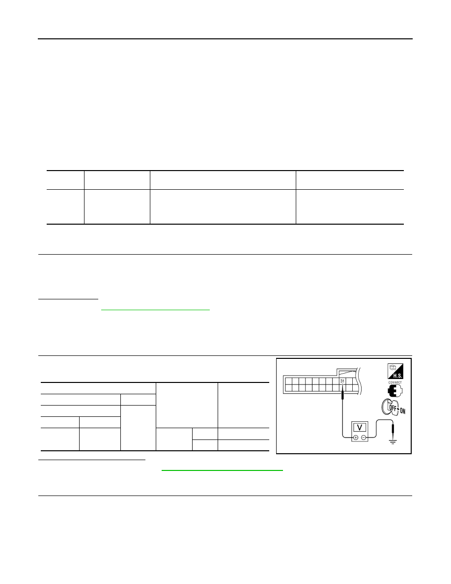
 CHECK IGNITION RELAY FEEDBACK INPUT SIGNAL

Check voltage between BCM harness connector and ground under

the following conditions.

Is the inspection result normal?

YES

>> Replace BCM. Refer to 

BCS-96, "Removal and Installation"

.

NO

>> GO TO 2

2.

 CHECK IGNITION RELAY FEEDBACK CIRCUIT

DTC No.

Trouble diagnosis 

name

DTC detecting condition

Possible cause

B2553

IGNITION RELAY

BCM detects a difference of signal for 2 seconds or 
more between the following information. 
• Ignition relay-2 (fuse block) ON/OFF operation
• Ignition relay-2 (fuse block) feedback.

• Harness or connectors

(ignition relay-2 feedback circuit is 
open or short)

Terminals

Condition

Voltage (V)

(+)

(-)

BCM

Ground

Connector

Terminal

M18

31

Ignition 

switch

OFF

0

ON

Battery voltage

ALMIA0086ZZ

PCS

B2553 IGNITION RELAY

PCS-61

< COMPONENT DIAGNOSIS >

[POWER DISTRIBUTION SYSTEM]

C

D

E

F

G

H

I

J

K

L

B

A

O

P

N

1. Turn ignition switch OFF.

2. Disconnect BCM and fuse block (J/B).

3. Check continuity between BCM harness connector and fuse

block harness connector.

4. Check continuity between BCM harness connector and ground.

Is the inspection result normal?

YES

>> GO TO 3

NO

>> Repair or replace harness.

3.

 CHECK INTERMITTENT INCIDENT

Refer to 

GI-42, "Intermittent Incident"

.

>> Inspection End.

BCM

Fuse block

Continuity

Connector

Terminal

Connector

Terminal

M18 (A)

31

M3 (B)

2N

Yes

ALMIA0087ZZ

BCM

Ground

Continuity

Connector

Terminal

M18

31

No

ALMIA0088ZZ

PCS-62

< COMPONENT DIAGNOSIS >

[POWER DISTRIBUTION SYSTEM]

B260A IGNITION RELAY

B260A IGNITION RELAY

Description

INFOID:0000000004202443

BCM turns ON the following relays to ignition power supply to each ECU when the ignition switch is turned

ON.

• Ignition relay-1 (inside IPDM E/R)

• Ignition relay-2 (inside fuse box)

• Blower fan motor relay

BCM checks any ignition relay ON request for consistency with the actual ignition relay operation status.

DTC Logic

INFOID:0000000004202444

DTC DETECTION LOGIC

NOTE:

• If DTC B260A is displayed with DTC U1000, first perform the trouble diagnosis for DTC U1000. Refer to

PCS-58, "DTC Logic"

.

• If DTC B260A is displayed with DTC U1010, first perform the trouble diagnosis for DTC U1010. Refer to

PCS-59, "DTC Logic"

.

• If DTC B260A is displayed with DTC B261A, first perform the trouble diagnosis for DTC B261A. Refer to

PCS-75, "DTC Logic"

.

DTC CONFIRMATION PROCEDURE

1.

 PERFORM DTC CONFIRMATION PROCEDURE

1. Turn ignition switch ON under the following conditions, and wait for at least 2 seconds.

-

CVT selector lever is in the P or N position.

-

Release the brake pedal.

2. Check “Self diagnostic result” with CONSULT-III. 
Is DTC detected?

YES

>> Go to 

PCS-62, "Diagnosis Procedure"

.

NO

>> Inspection End.

Diagnosis Procedure

INFOID:0000000004202445

1.

 CHECK DTC WITH IPDM E/R

Check “Self diagnostic result” with CONSULT-III. Refer to 

PCS-45, "DTC Index"

.

Is DTC detected?

YES

>> Replace IPDM E/R. Refer to 

PCS-48, "Removal and Installation"

.

NO

>> GO TO 2

2.

 CHECK INTERMITTENT INCIDENT

Refer to 

GI-42, "Intermittent Incident"

.

>> Inspection End.

DTC No.

Trouble diagnosis 

name

DTC detecting condition

Possible cause

B260A

IGNITION RELAY

BCM detects a difference of signal for 2 second or 
more between the following information.
• Ignition relay-1 (ON/OFF) operation
• Ignition relay-1 feedback

• Harness or connectors

(Ignition relay-1 operation circuit is 
open or shorted.)

PCS

B2611 ACC RELAY

PCS-63

< COMPONENT DIAGNOSIS >

[POWER DISTRIBUTION SYSTEM]

C

D

E

F

G

H

I

J

K

L

B

A

O

P

N

B2611 ACC RELAY

Description

INFOID:0000000004202446

BCM turns ON the ACC relay to supply ACC power to each ECU when the power supply position changes to

ACC.

BCM check ACC relay ON request for consistency with the actual ACC relay operation status.

DTC Logic

INFOID:0000000004202447

DTC DETECTION LOGIC

NOTE:

• If DTC B2611 is displayed with DTC U1000, first perform the trouble diagnosis for DTC U1000. Refer to

PCS-58, "DTC Logic"

 .

• If DTC B2611 is displayed with DTC U1010, first perform the trouble diagnosis for DTC U1010. Refer to

PCS-59, "DTC Logic"

.

DTC CONFIRMATION PROCEDURE

1.

 PERFORM DTC CONFIRMATION PROCEDURE

1. Turn the power supply position to ACC under the following conditions, and wait for at least 2 seconds.

-

CVT selector lever is in P or N position

-

Brake not depressed

2. Check “Self diagnostic result” with CONSULT-III.
Is DTC detected?

YES

>> Go to 

PCS-63, "Diagnosis Procedure"

.

NO

>> Inspection End.

Diagnosis Procedure

INFOID:0000000004202448

1.

CHECK ACC RELAY FEED BACK INPUT SIGNAL

Check voltage between BCM harness connector and ground under

the following conditions.

Is the inspection result normal?

YES

>> GO TO 5

NO

>> GO TO 2

2.

CHECK ACC RELAY POWER SUPPLY CIRCUIT

DTC No.

Trouble diagnosis 

name

DTC detecting condition

Possible cause

B2611

ACC RELAY

BCM detects a difference of signal for 2 seconds or 
more between the following information.
• ACC relay ON/OFF operation 
• ACC relay feedback.

• Harness or connectors

(ACC relay feed back circuit is 
open or shorted)

Terminals

Condition

Voltage (V)

(+)

(-)

BCM

Ground

Connector

Terminal

M18

30

Ignition 

switch

OFF

0

ACC

Battery volt-

age

ALMIA0089ZZ


Content   ..  997  998  999  1000   ..