Nissan Altima L32. Manual - part 946


  Index      Nissan     Nissan Altima L32 (2007-2009 year) - Service and Repair Manual


Search            


Content   ..  944  945  946  947   ..


Nissan Altima L32. Manual - part 946


MWI-36

< FUNCTION DIAGNOSIS >

COMPASS

COMPASS

Description

INFOID:0000000004204082

DESCRIPTION

With the ignition switch in the ON position, and the mode (N) switch

ON, the compass display will indicate the direction the vehicle is

heading.

Vehicle direction is displayed as follows:

• N: north

• E: east

• S: south

• W:  west

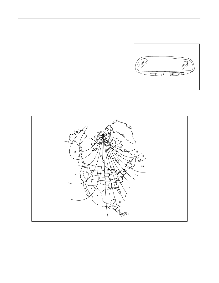
ZONE VARIATION SETTING PROCEDURE

The difference between magnetic north and geographical north can sometimes be great enough to cause

false compass readings. This difference is known as variance. In order for the compass to operate properly

(accurately) in a particular zone, the zone variation must be calibrated using the following procedure. 

Zone Variation Chart

1. Determine your location on the zone map.
2. Turn the ignition switch to the ON position.
3. Press and hold the mode (N) switch for about 5 seconds. The current zone number will appear in the dis-

play.

4. Press the mode (N) switch repeatedly until the desired zone number appears in the display.
Once the desired zone number is displayed, stop pressing the mode (N) switch and the display will show a

compass direction after a few seconds.

NOTE:

Use zone number 5 for Hawaii.

CALIBRATION PROCEDURE

LKIA0447E

WKIA4148E

MWI

COMPASS

MWI-37

< FUNCTION DIAGNOSIS >

C

D

E

F

G

H

I

J

K

L

M

B

A

O

P

The compass display is equipped with an automatic correction function. If the compass display reads “C” or

the direction is not shown correctly, perform the correction procedure below.

1. Press and hold the mode (N) switch for about 9 seconds. The

display will read “C”.

2. Drive the vehicle slowly in a circle, in an open, safe place. The

initial calibration is completed in about three turns.

NOTE:

In places where the terrestrial magnetism is extremely disturbed, the

initial correction may start automatically.

LKIA0447E

MWI-38

< FUNCTION DIAGNOSIS >

DIAGNOSIS SYSTEM (METER)

DIAGNOSIS SYSTEM (METER)

Diagnosis Description

INFOID:0000000004204083

SELF-DIAGNOSIS MODE

• Odo/trip meter and information display segment operation can be checked in self-diagnosis mode.

• Meters/gauges can be checked in self-diagnosis mode.

OPERATION PROCEDURE

1. Turn the ignition switch OFF.
2. While pushing the odo/trip meter switch, turn the ignition switch ON again.
3. Push the odo/trip meter switch at least 3 times within 7 seconds after the ignition switch is turned ON.
4. The unified meter control unit is turned to self-diagnosis mode.

• All the segments on the odo/trip meter illuminate.

• Dots in all segments of information display LCD (1) flash alter-

nately.

NOTE:

If any of the segments are not displayed, replace the combina-

tion meter. Refer to 

MWI-176, "Removal and Installation"

.

5. Push the odo/trip meter switch. Each meter/gauge should indicate as shown in the figure.

CONSULT-III Function (METER/M&A)

INFOID:0000000004204084

CONSULT-III can display each diagnostic item using the diagnostic test modes shown following.

SKIB1206J

JSNIA0020GB

ALNIA0011ZZ

MWI

DIAGNOSIS SYSTEM (METER)

MWI-39

< FUNCTION DIAGNOSIS >

C

D

E

F

G

H

I

J

K

L

M

B

A

O

P

SELF-DIAG RESULTS

Display Item List

Refer to 

MWI-95, "DTC Index"

.

DATA MONITOR

Display Item List

X: Applicable

METER/M&A diagnosis mode

Description

SELF-DIAG RESULTS

Displays combination meter self-diagnosis results.

DATA MONITOR

Displays combination meter input/output data in real time.

CAN DIAG SUPPORT MNTR

The result of transmit/receive diagnosis of CAN communication can be read.

Display item [Unit]

MAIN

SIGNALS

SELECTION 

FROM MENU

Description

SPEED METER [km/h] or [mph]

X

X

Displays the value of vehicle speed signal.

SPEED OUTPUT [km/h] or [mph]

X

X

Displays the value of vehicle speed signal, which is transmitted to 
each unit with CAN communication.

ODO OUTPUT

X

Displays the value, which is calculated by vehicle speed signal.

TACHO METER [rpm]

X

X

Displays the value of engine speed signal, which is input from ECM.

FUEL METER [lit.]

X

X

Displays the value, which processes a resistance signal from fuel 
gauge.

W TEMP METER [

°C] or [°F]

X

X

Displays the value of engine coolant temperature signal, which is in-
put from ECM. 

ABS W/L [ON/OFF]

X

Displays [ON/OFF] condition of ABS warning lamp.

VDC/TCS IND [ON/OFF]

X

Displays [ON/OFF] condition of VDC/TCS OFF indicator lamp.

SLIP IND [ON/OFF]

X

Displays [ON/OFF] condition of SLIP indicator lamp.

BRAKE W/L [ON/OFF]

X

Displays [ON/OFF] condition of brake warning lamp.*

DOOR W/L [ON/OFF]

X

Displays [ON/OFF] condition of door warning lamp.

TRUNK/GLAS-H [ON/OFF]

X

Displays [ON/OFF] condition of trunk warning lamp.

HI-BEAM IND [ON/OFF]

X

Displays [ON/OFF] condition of high beam indicator.

TURN IND [ON/OFF]

X

Displays [ON/OFF] condition of turn indicator.

OIL W/L [ON/OFF]

X

Displays [ON/OFF] condition of oil pressure warning lamp.

MIL [ON/OFF] 

X

Displays [ON/OFF] condition of malfunction indicator lamp.

CRUISE IND [ON/OFF]

X

Displays [ON/OFF] condition of CRUISE indicator.

SET IND [ON/OFF]

X

Displays [ON/OFF] condition of SET indicator.

ATC/T-AMT W/L [ON/OFF]

X

Displays [ON/OFF] condition of AT CHECK warning lamp.

FUEL W/L [ON/OFF]

X

Displays [ON/OFF] condition of low-fuel warning lamp.

WASHER W/L [ON/OFF]

X

Displays [ON/OFF] condition of low-washer fluid warning lamp.

AIR PRES W/L [ON/OFF]

X

Displays [ON/OFF] condition of tire pressure warning lamp.

KEY G W/L [ON/OFF]

X

Displays [ON/OFF] condition of key warning lamp.

LCD

X

Displays the value of Intelligent Key system message indication.

SHIFT IND [P, R, N, D, L]

X

Displays [P, R, N, D, L] range position of CVT.

M RANGE SW [ON/OFF]

X

Displays [ON/OFF] condition of manual mode range switch.

NM RANGE SW [ON/OFF]

X

Displays [ON/OFF] condition of except for manual mode range 
switch.

AT SFT UP SW [ON/OFF]

X

Displays [ON/OFF] condition of A/T shift-up switch.

AT SFT DWN SW [ON/OFF]

X

Displays [ON/OFF] condition of A/T shift-down switch.


Content   ..  944  945  946  947   ..