Nissan Altima L32. Manual - part 669


  Index      Nissan     Nissan Altima L32 (2007-2009 year) - Service and Repair Manual


Search            


Content   ..  667  668  669  670   ..


Nissan Altima L32. Manual - part 669


EM-212

< DISASSEMBLY AND ASSEMBLY >

[VQ35DE]

CYLINDER BLOCK

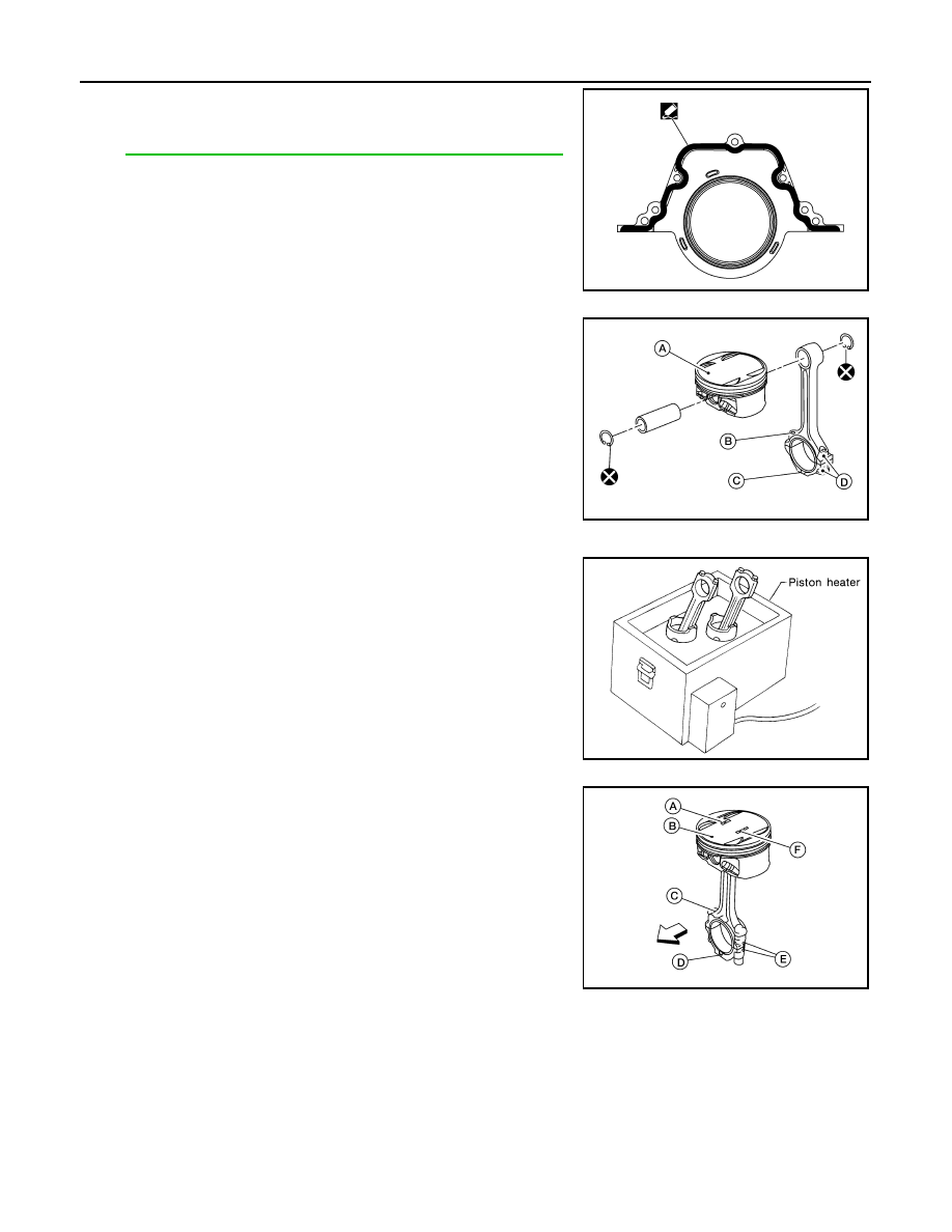
9. Install the rear oil seal retainer.

• Apply sealant to rear oil seal retainer as shown.

Use Genuine Silicone RTV Sealant, or equivalent. Refer to

GI-15, "Recommended Chemical Products and Sealants"

.

10. Install the piston to the connecting rod. 
a. Using suitable snap ring pliers, install the snap ring fully into the

pin-groove of the piston rear side. 

• Piston front mark (A)

• Oil hole (B)

• Connecting rod front mark (C)

• Cylinder No. (D)

b. Install the piston to the connecting rod.

• Heat the piston until the piston pin can be pushed in by hand

without excess force [approx. 60

° - 70°C (140° to 158°F)].

From the front to the rear, insert the piston pin into the piston

and through the connecting rod.

• Assemble so that the piston front mark (B) on the crown and

the oil hole (C), connecting rod front mark (D) and Cylinder No.

(E) on the are positioned as shown.

-

⇐: Front

- Piston grade number (A)

- Pin grade number (F)

AWBIA0028ZZ

AWBIA0026ZZ

SEM965A

AWBIA0027ZZ

CYLINDER BLOCK

EM-213

< DISASSEMBLY AND ASSEMBLY >

[VQ35DE]

C

D

E

F

G

H

I

J

K

L

M

A

EM

N

P

O

c. Install the snap ring into the front of the piston pin-groove. 

• After installing, check that the connecting rod pivots smoothly

on the pin.

CAUTION:

Do not reuse snap rings, always replace with new ones.

11. Using a piston ring expander, install the piston rings. 

CAUTION:

• Be careful not to damage the piston.

• When the piston rings are not replaced, remount the rings

in their original positions.

• When replacing the piston rings, those without stamped

surface (A) can be mounted either side up.

• Install the second ring with the stamped surface (B) facing

upward. If the ring is not stamped it can face in either

direction.

• Position each ring with the gap as shown, referring to the pis-

ton front mark.

12. Install the connecting rod bearings to the connecting rod and the

connecting rod cap.

• When installing the connecting rod bearings, apply engine oil

to the bearing surface (crankshaft side). Do not apply oil to the

back surface (connecting rod and cap side), but thoroughly

clean it. 

• When installing, align the connecting rod bearing protrusion

with the notch of the connecting rod to install. 

• Check that the oil holes on the connecting rod and on the cor-

responding bearing are aligned. 

PBIC0260E

Top ring (A)

: —

Second ring (B)

: 2A

JPBIA0263ZZ

PBIC0808E

PBIC0266E

EM-214

< DISASSEMBLY AND ASSEMBLY >

[VQ35DE]

CYLINDER BLOCK

13. Install the piston and connecting rod assembly into the corre-

sponding cylinder. 

• Position the crankshaft pin corresponding to the connecting

rod to be installed onto the bottom dead center. 

• Apply engine oil sufficiently to the cylinder bore, piston, and

crankshaft pin. 

• Match the cylinder position with the cylinder No. (B) on the

connecting rod to install. 

• Install the piston with the piston front mark (A) on the crown

facing the front of the engine (

), using a suitable tool. 

- Oil hole (C)

CAUTION:

Be careful not to damage the crankshaft pin and cylinder wall, resulting from an interference of the

connecting rod big end.

14. Install the connecting rod cap. 

• Match the stamped cylinder number marks on the connecting

rod with those on the cylinder cap for installation.   

• Install the piston connecting rod assembly and cap so that the

front mark on the cap and piston are facing the front of the

engine.

• Lubricate the threads and seat surfaces with new engine

oil.

15. Check the connecting rod cap bolts before reusing, then install

in their original position in the connecting rod. The bolts should

screw in smoothly by hand.

• Measure the outer diameter of the connecting rod cap bolt as

shown.

16. Tighten the connecting rod nuts in two stages using Tool:

CAUTION:

Always use either an angle wrench or protractor. Avoid

tightening based on visual check alone.

• Apply engine oil to the threads and seats of the connecting rod

bolts and nuts. 

• After tightening the nuts, make sure that the crankshaft rotates

smoothly. 

• Check the connecting rod side clearance. If beyond the limit, replace the connecting rod and/or crank-

shaft.

AWBIA0029ZZ

SEM457G

Outer diameter (d) of the connecting rod bolt
Standard

: 7.90 - 8.00 mm (0.3110 - 0.3150 in)

Limit

: 7.75 mm (0.3051 in)

SEM538G

Stage 1

: 19 - 21 N·m (1.9 - 2.1 kg-m, 14 - 15 ft-lb)

Stage 2

: 90

° - 95° degrees clockwise

Tool number

: KV10112100 (BT-8653-A)

Connecting rod side clearance:
Standard

: 0.20 - 0.35 mm (0.0079 - 0.0138 in)

Limit

: 0.40 mm (0.0157 in)

SEM953E

CYLINDER BLOCK

EM-215

< DISASSEMBLY AND ASSEMBLY >

[VQ35DE]

C

D

E

F

G

H

I

J

K

L

M

A

EM

N

P

O

17. Install the baffle plate to the main bearing beam.
18. Install the knock sensor.

• Make sure that there is no foreign material on the cylinder

block mating surface and the back surface of the knock sen-

sor. 

• Install the knock sensor with the connector facing the rear of

the engine. 

• Do not tighten the bolts while holding the connector.   

• Make sure that the knock sensor does not interfere with other

parts.

CAUTION:

If any impact by dropping occurs to the knock sensor,

replace it with new one.

19. Install the pilot bushing (M/T) or converter (CVT) as shown.

20. Install the flywheel (M/T), if equipped.

• When installing flywheel to crankshaft, be sure to correctly

align crankshaft side dowel pin and flywheel side dowel pin

hole.

21. Install the drive plate (CVT), if equipped.

• Install the drive plate and reinforce plate in the direction as

shown.

• Align dowel pins of crankshaft rear and drive plate with pin

holes of each part.

• Secure the crankshaft using a ring gear stopper.

• Tighten the drive plate bolts in one or two steps.

22. Install the cylinder head. Refer to 

EM-191, "Removal and Instal-

lation"

.

23. Install the timing chain. Refer to 

EM-166, "Installation"

.

24. Install the oil pan. Refer to 

EM-139, "Removal and Installation"

.

25. Remove the engine from the stand and install the engine assembly into the vehicle. Refer to 

EM-202,

"Removal and Installation"

.

26. Assembly of the remaining parts is in the reverse order of disassembly.
27. Fill the engine with the specified oil and coolant. Refer to 

MA-12, "Engine Oil Recommendation"

 and 

MA-

12, "Fluids and Lubricants"

.

CAUTION:

Wait at least 30 minutes for the sealant to set-up before filling the engine with fluids and running it.

PBIC0810E

SEM163B

SEM916G

PBIC0910E


Content   ..  667  668  669  670   ..