Nissan Altima L32. Manual - part 664


  Index      Nissan     Nissan Altima L32 (2007-2009 year) - Service and Repair Manual


Search            


Content   ..  662  663  664  665   ..


Nissan Altima L32. Manual - part 664


EM-192

< ON-VEHICLE REPAIR >

[VQ35DE]

CYLINDER HEAD

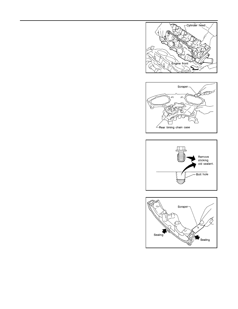
4. Remove cylinder heads and gaskets.

• Discard the cylinder head gaskets and use new gaskets for

installation.

INSTALLATION

1. Before installing the rear timing chain case, remove the old Sili-

cone RTV Sealant from mating surface using a scraper.

• Also remove old sealant from mating surface of cylinder block.

• Remove the old Silicone RTV Sealant from the bolt hole and

thread.

2. Before installing the front cam bracket, remove the old RTV Sili-

cone Sealant from the mating surface using a scraper.

• Do not scratch the mating surface.

SEM863E

SEM891E

SEM161F

SEM892E

CYLINDER HEAD

EM-193

< ON-VEHICLE REPAIR >

[VQ35DE]

C

D

E

F

G

H

I

J

K

L

M

A

EM

N

P

O

3. Turn the crankshaft until No. 1 piston is set at TDC on the com-

pression stroke.

• The crankshaft key should line up with the right bank cylinder

center line as shown.

4. Install new gaskets on the cylinder heads.

CAUTION:

Do not rotate crankshaft and camshaft separately or valves

will strike piston heads.

5. Inspect the cylinder head bolts before installing the cylinder heads.

CAUTION:

Cylinder head bolts are tightened by degree rotation tight-

ening method. Whenever the size difference between d1

and d2 exceeds the limit, replace the bolts with new ones.

• Lubricate threads and seat surfaces of the bolts with new

engine oil.

6. Install the cylinder heads on the cylinder block. Tighten the cylin-

der head bolts in the five steps in the numerical order as shown

using Tool.

• Tightening procedure:

SEM532G

SEM445G

Limit (d1 - d2)

: 0.11 mm (0.0043 in)

SEM957E

Tool Number

: KV10112100 (BT-8653-A)

SEM879EA

EM-194

< ON-VEHICLE REPAIR >

[VQ35DE]

CYLINDER HEAD

7. Installation of the remaining components is in the reverse order of removal.

Cylinder head bolts
Step a

: 98.1 N·m (10 kg-m, 72 ft-lb)

Step b

:Loosen in the reverse order of tightening

Step c  : 32.9 N·m (4.0 kg-m, 29 ft-lb)
Step d

: 90

° degrees rotation clockwise

Step e

: 90

° degrees rotation clockwise

SEM877EA

SEM878EA

CYLINDER HEAD

EM-195

< ON-VEHICLE REPAIR >

[VQ35DE]

C

D

E

F

G

H

I

J

K

L

M

A

EM

N

P

O

Disassembly and Assembly

INFOID:0000000004202179

CAUTION:

• When installing camshafts, chain tensioners, oil seals, or other sliding parts, lubricate contacting

surfaces with new engine oil.

• Apply new engine oil to threads and seat surface when installing cylinder head, camshaft sprocket,

crankshaft pulley, and camshaft bracket.

• Attach tags to valve lifters so as not to mix them up.

ALBIA0261ZZ

1.

Valve collet

2.

Valve spring retainer

3.

Valve spring

4.

Valve oil seal

5.

Valve spring seat

6.

Valve guide

7.

Cylinder head

8.

Valve seat (EXH)

9.

Valve seat (INT)

10. Valve (EXH)

11. Valve (INT)


Content   ..  662  663  664  665   ..