Nissan Altima L32. Manual - part 589


  Index      Nissan     Nissan Altima L32 (2007-2009 year) - Service and Repair Manual


Search            


Content   ..  587  588  589  590   ..


Nissan Altima L32. Manual - part 589


COOLING FAN

EC-1477

< COMPONENT DIAGNOSIS >

[VQ35DE]

C

D

E

F

G

H

I

J

K

L

M

A

EC

N

P

O

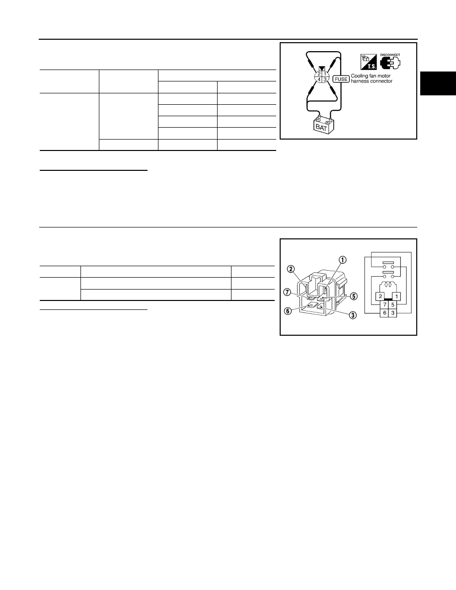
3. Supply cooling fan motor terminals with battery voltage and

check operation.

Check that cooling fan speed of condition B is higher than that of A.

Is the inspection result normal?

YES

>> INSPECTION END

NO

>> Replace cooling fan motor.

Component Inspection (Cooling Fan Relay)

INFOID:0000000004362355

1.

CHECK COOLING FAN RELAY

1. Disconnect cooling fan relays -2, -3 harness connectors.

2. Check continuity between cooling fan relay -2, -3 terminals

under the following conditions.

Is the inspection result normal?

YES

>> INSPECTION END

NO

>> Replace cooling fan relay.

Condition

Terminals

+

Cooling fan motor

A

1

3 and 4

2

3 and 4

1 and 2

3

1 and 2

4

B

1,  2

3,  4

SEF734W

Terminals

Conditions

Continuity

3 and 5
6 and 7

12 V direct current supply between terminals 1 and 2

Existed

No current supply

Not existed

SEF745U

EC-1478

< COMPONENT DIAGNOSIS >

[VQ35DE]

ELECTRICAL LOAD SIGNAL

ELECTRICAL LOAD SIGNAL

Description

INFOID:0000000004362356

The electrical load signal (Headlamp switch signal, rear window defogger switch signal, etc.) is transferred via

the CAN communication.

Component Function Check

INFOID:0000000004362357

1.

CHECK REAR WINDOW DEFOGGER SWITCH FUNCTION

1. Turn ignition switch ON.

2. Connect CONSULT-III and select “DATA MONITOR” mode.

3. Select “LOAD SIGNAL” and check indication under the following conditions.

Is the inspection result normal?

YES

>> GO TO 2.

NO

>> Go to 

EC-1478, "Diagnosis Procedure"

.

2.

CHECK LIGHTING SWITCH FUNCTION

Check “LOAD SIGNAL” indication under the following conditions.

Is the inspection result normal?

YES

>> GO TO 3.

NO

>> Go to 

EC-1478, "Diagnosis Procedure"

.

3.

CHECK HEATER FAN CONTROL SWITCH FUNCTION

Select “HEATER FAN SW” and check indication under the following conditions.

Is the inspection result normal?

YES

>> INSPECTION END

NO

>> Go to 

EC-1478, "Diagnosis Procedure"

.

Diagnosis Procedure

INFOID:0000000004362358

1.

INSPECTION START

Confirm the malfunctioning circuit (rear window defogger, headlamp or heater fan). Refer to 

EC-1478, "Com-

ponent Function Check"

.

Which circuit is related to the incident?

Rear window defogger>>GO TO 2.

Headlamp>>GO TO 3.

Heater fan>>GO TO 4.

2.

CHECK REAR WINDOW DEFOGGER SYSTEM

Refer to 

DEF-3, "Work Flow"

.

Monitor item

Condition

Indication

LOAD SIGNAL

Rear window defogger switch

ON

ON

OFF

OFF

Monitor item

Condition

Indication

LOAD SIGNAL

Lighting switch

ON at 2nd position

ON

OFF

OFF

Monitor item

Condition

Indication

HEATER FAN SW

Heater fan control switch

ON

ON

OFF

OFF

ELECTRICAL LOAD SIGNAL

EC-1479

< COMPONENT DIAGNOSIS >

[VQ35DE]

C

D

E

F

G

H

I

J

K

L

M

A

EC

N

P

O

>> INSPECTION END

3.

CHECK HEADLAMP SYSTEM

Refer to 

EXL-4, "Work Flow"

.

>> INSPECTION END

4.

CHECK HEATER FAN CONTROL SYSTEM

Refer to 

HAC-4, "Work Flow"

 (automatic air conditioner) or 

HAC-101, "Work Flow"

 (manual air conditioner).

>> INSPECTION END

EC-1480

< COMPONENT DIAGNOSIS >

[VQ35DE]

ELECTRONIC CONTROLLED ENGINE MOUNT

ELECTRONIC CONTROLLED ENGINE MOUNT

Description

INFOID:0000000004362359

The electronic controlled engine mount control solenoid valve controls the intake manifold vacuum signal for

electronic controlled engine mount. The electronic controlled engine mount control solenoid valve is moved by

ON/OFF signal from the ECM. When the solenoid is OFF, the vacuum signal from the intake manifold is cut.

When the solenoid is ON, the intake manifold vacuum signal is sent to the electronic controlled engine mount. 

Component Function Check

INFOID:0000000004362360

1.

CHECK OVERALL FUNCTION

1. Start engine and warm it up to normal operating temperature.

2. Shift selector lever to D position (CVT) or 1st position (M/T) while depressing the brake pedal and parking

brake pedal.

3. Disconnect electronic controlled engine mount control solenoid valve harness connector.

4. Check that body vibration increases compared to the condition of step 2 above (with vehicle stopped).
Is the inspection result normal?

YES

>> INSPECTION END

NO

>>

EC-1480, "Diagnosis Procedure"

.

Diagnosis Procedure

INFOID:0000000004362361

1.

CHECK VACUUM SOURCE

1. Turn ignition switch OFF.

2. Reconnect electronic controlled engine mount control solenoid valve harness connector.

3. Disconnect vacuum hose connected to electronic controlled engine mount.

4. Start engine and let it idle.

5. Check vacuum hose for vacuum existence.

Is the inspection result normal?

YES

>> GO TO 7.

NO

>> GO TO 2.

2.

CHECK VACUUM HOSES AND VACUUM GALLERY

1. Turn ignition switch OFF.

2. Check vacuum hoses and vacuum gallery for clogging, cracks or improper connection. Refer to 

EC-1107,

"System Description"

.

Is the inspection result normal?

YES

>> GO TO 3.

NO

>> Repair or replace vacuum hoses and vacuum gallery.

3.

CHECK ELECTRONIC CONTROLLED ENGINE MOUNT CONTROL SOLENOID VALVE POWER SUPPLY

CIRCUIT
1. Disconnect electronic controlled engine mount control solenoid valve harness connector.

2. Turn ignition switch ON.

3. Check the voltage between front electronic controlled engine

mount harness connector and ground.

Is the inspection result normal?

YES

>> GO TO 5.

Vacuum should exist.

Electronic controlled engine mount 

control solenoid valve

Ground

Voltage

Connector

Terminal

F64

1

Ground

Battery voltage

SEF206W


Content   ..  587  588  589  590   ..