Nissan Altima L32. Manual - part 498
ELECTRONIC CONTROLLED ENGINE MOUNT
EC-1113
< FUNCTION DIAGNOSIS >
[VQ35DE]
C
D
E
F
G
H
I
J
K
L
M
A
EC
N
P
O
1.
A/F sensor 1 (bank 1)
2.
A/F sensor 1 (bank 2)
3.
HO2S2 (bank 1) harness connector
4.
HO2S2 (bank 2) harness connector
(CVT models)
5.
Front engine mount
6.
HO2S2 (bank 2) harness connector
(M/T models)
7.
Crankshaft position sensor (POS)
(M/T models)
8.
Crankshaft position sensor (POS)
(CVT models)
: Vehicle front
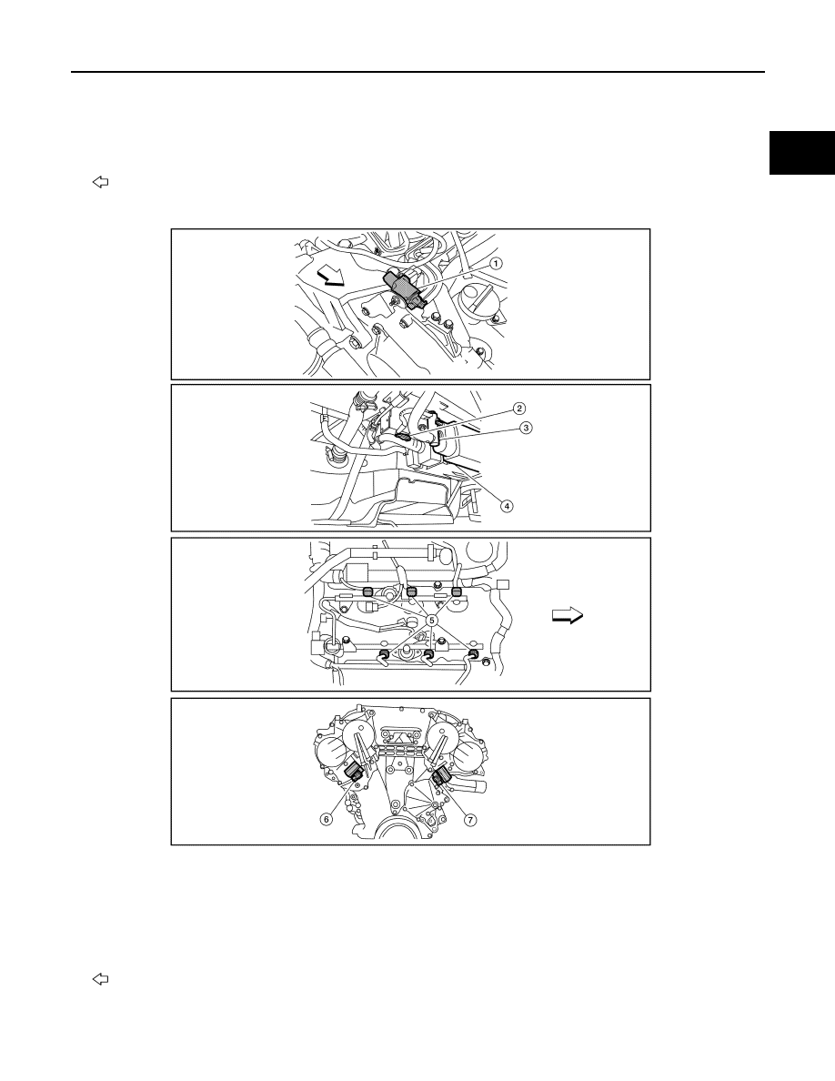
1.
Electronic controlled engine mount
control solenoid valve
2.
EVAP control system pressure sen-
sor
3.
EVAP canister vent control valve
4.
EVAP canister
5.
Injector harness connector
6.
Intake valve timing control solenoid
valve (bank 1)
7.
Intake valve timing control solenoid
valve (bank 2)
: Vehicle front
ALBIA0103ZZ