Nissan Altima L32. Manual - part 444
P1564 ASCD STEERING SWITCH
EC-897
< COMPONENT DIAGNOSIS >
[QR25DE EXCEPT FOR CALIFORNIA]
C
D
E
F
G
H
I
J
K
L
M
A
EC
N
P
O
2. Select “MAIN SW”, “CANCEL SW”, “RESUME/ACC SW” and “SET SW” in “DATA MONITOR” mode with
CONSULT-III.
3. Check each item indication under the following conditions.
Without CONSULT-III
1. Turn ignition switch ON.
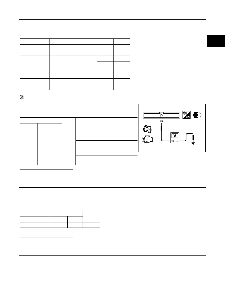
2. Check the voltage between ECM harness connector and
ground.
Is the inspection result normal?
YES
>> GO TO 8.
NO
>> GO TO 3.
3.
CHECK ASCD STEERING SWITCH GROUND CIRCUIT FOR OPEN AND SHORT
1. Turn ignition switch OFF.
2. Disconnect ECM harness connector.
3. Disconnect combination switch harness connector M88.
4. Check the continuity between combination switch and ECM harness connector.
5. Also check harness for short to ground and short to power.
Is the inspection result normal?
YES
>> GO TO 5.
NO
>> GO TO 4.
4.
DETECT MALFUNCTIONING PART
Check the following.
• Harness connectors M1, E30
• Combination switch (spiral cable)
• Harness for open and short between ECM and combination switch
Monitor item
Condition
Indication
MAIN SW
MAIN switch
Pressed
ON
Released
OFF
CANCEL SW
CANCEL switch
Pressed
ON
Released
OFF
RESUME/ACC SW RESUME/ACCELERATE switch
Pressed
ON
Released
OFF
SET SW
SET/COAST switch
Pressed
ON
Released
OFF
ECM
Ground
Condition
Voltage
Connector
Terminal
E10
85
(ASCD steering
switch signal)
Ground
MAIN switch: Pressed
Approx. 0V
CANCEL switch: Pressed
Approx. 1V
SET/COAST switch: Pressed Approx. 2V
RESUME/ACCELERATE
switch: Pressed
Approx. 3V
All ASCD steering switches:
Released
Approx. 4V
PBIB3600E
Combination switch
ECM
Continuity
Terminal
Connector Terminal
16
E10
92
Existed