Nissan Altima L32. Manual - part 441
P1550 BATTERY CURRENT SENSOR
EC-885
< COMPONENT DIAGNOSIS >
[QR25DE EXCEPT FOR CALIFORNIA]
C
D
E
F
G
H
I
J
K
L
M
A
EC
N
P
O
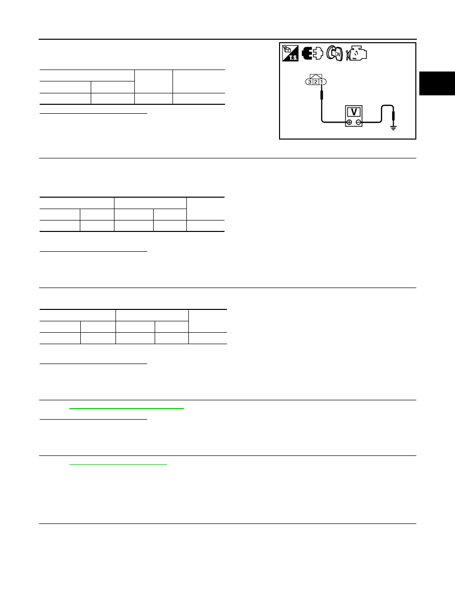
3. Check the voltage between battery current sensor harness con-
nector and ground.
Is the inspection result normal?
YES
>> GO TO 3.
NO
>> Repair open circuit or sort to ground or short to power in
harness or connectors.
3.
CHECK BATTERY CURRENT SENSOR GROUND CIRCUIT FOR OPEN AND SHORT
1. Turn ignition switch OFF.
2. Disconnect ECM harness connector.
3. Check the continuity between battery current sensor harness connector and ECM harness connector.
4. Also check harness for short to ground and short to power.
Is the inspection result normal?
YES
>> GO TO 4.
NO
>> Repair open circuit or sort to ground or short to power in harness or connectors.
4.
CHECK BATTERY CURRENT SENSOR INPUT SIGNAL CIRCUIT FOR OPEN AND SHORT
1. Check the continuity between battery current sensor harness connector and ECM harness connector.
2. Also check harness for short to ground and short to power.
Is the inspection result normal?
YES
>> GO TO 5.
NO
>> Repair open circuit or sort to ground or short to power in harness or connectors.
5.
CHECK BATTERY CURRENT SENSOR
EC-885, "Component Inspection"
Is the inspection result normal?
YES
>> GO TO 6.
NO
>> Replace battery negative cable assembly.
6.
CHECK INTERMITTENT INCIDENT
GI-42, "Intermittent Incident"
.
>> INSPECTION END
Component Inspection
INFOID:0000000004349858
1.
CHECK BATTERY CURRENT SENSOR
1. Reconnect harness connectors disconnected.
Battery current sensor
Ground
Voltage
Connector
Terminal
F5
1
Ground
Approx. 5V
JMBIA1602ZZ
Battery current sensor
ECM
Continuity
Connector
Terminal
Connector
Terminal
F5
2
F13
44
Existed
Battery current sensor
ECM
Continuity
Connector
Terminal
Connector
Terminal
F5
3
F13
42
Existed