Nissan Altima L32. Manual - part 425
P0448 EVAP CANISTER VENT CONTROL VALVE
EC-821
< COMPONENT DIAGNOSIS >
[QR25DE EXCEPT FOR CALIFORNIA]
C
D
E
F
G
H
I
J
K
L
M
A
EC
N
P
O
4. Check air passage continuity and operation delay time.
Make sure new O-ring is installed properly.
Operation takes less than 1 second.
Without CONSULT-III
Check air passage continuity and operation delay time under the fol-
lowing conditions.
Make sure new O-ring is installed properly.
Operation takes less than 1 second.
Is the inspection result normal?
YES
>> INSPECTION END
NO
>> Replace EVAP canister vent control valve
3.
CHECK EVAP CANISTER VENT CONTROL VALVE-III
With CONSULT-III
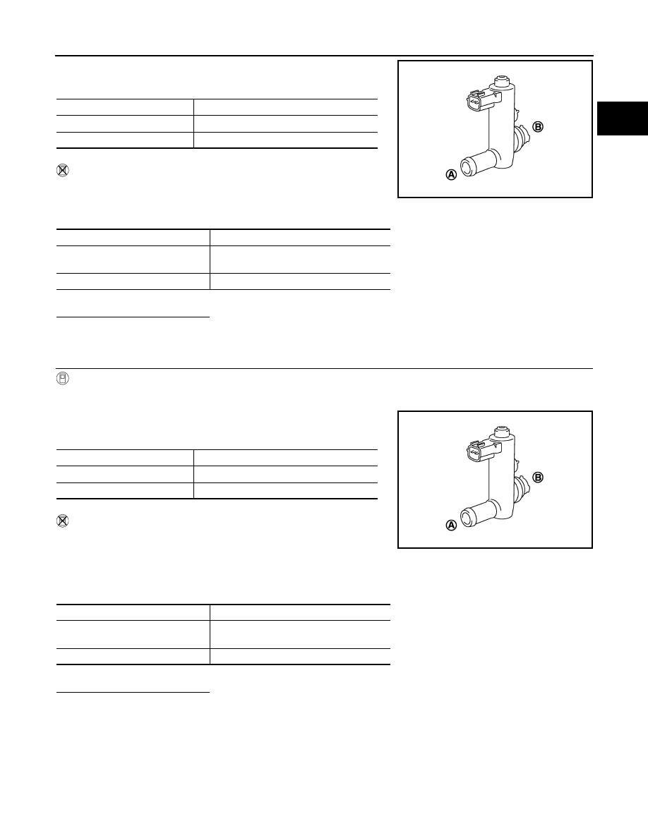
1. Clean the air passage [portion (A) to (B)] of EVAP canister vent control valve using an air blower.
2. Perform “VENT CONTROL/V” in “ACTIVE TEST” mode.
3. Check air passage continuity and operation delay time.
Make sure new O-ring is installed properly.
Operation takes less than 1 second.
Without CONSULT-III
1. Clean the air passage [portion (A) to (B)] of EVAP canister vent
control valve using an air blower.
2. Check air passage continuity and operation delay time under the
following conditions.
Make sure new O-ring is installed properly.
Operation takes less than 1 second.
Is the inspection result normal?
YES
>> INSPECTION END
NO
>> GO TO 3.
Condition VENT CONTROL/V
Air passage continuity between (A) and (B)
ON
Not existed
OFF
Existed
Condition
Air passage continuity between (A) and (B)
12V direct current supply between
terminals (1) and (2)
Not existed
OFF
Existed
JMBIA0169ZZ
Condition VENT CONTROL/V
Air passage continuity between (A) and (B)
ON
Not existed
OFF
Existed
Condition
Air passage continuity between (A) and (B)
12V direct current supply between
terminals (1) and (2)
Not existed
OFF
Existed
JMBIA0169ZZ