Nissan Altima L32. Manual - part 392


  Index      Nissan     Nissan Altima L32 (2007-2009 year) - Service and Repair Manual


Search            


Content   ..  390  391  392  393   ..


Nissan Altima L32. Manual - part 392


P0037, P0038 HO2S2 HEATER

EC-689

< COMPONENT DIAGNOSIS >

[QR25DE EXCEPT FOR CALIFORNIA]

C

D

E

F

G

H

I

J

K

L

M

A

EC

N

P

O

CAUTION:

• Discard any sensor which has been dropped from a height of more than 0.5 m (19.7 in) onto a hard

surface such as a concrete floor; use a new one.

• Before installing new sensor, clean exhaust system threads using oxygen sensor thread cleaner tool

[commercial service tool: (J-43897-18) or J43897-12] and approved anti-seize lubricant (commercial

service tool).

>> INSPECTION END

7.

CHECK INTERMITTENT INCIDENT

Refer to 

GI-42, "Intermittent Incident"

.

>> INSPECTION END

Component Inspection

INFOID:0000000004349656

1.

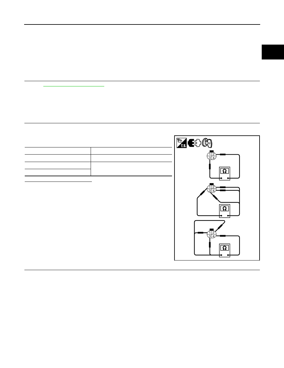
CHECK HEATED OXYGEN SENSOR 2 HEATER

1. Turn ignition switch OFF.

2. Disconnect heated oxygen sensor 2 harness connector.

3. Check resistance between HO2S2 terminals as follows.

Is the inspection result normal?

YES

>> INSPECTION END

NO

>> GO TO 2.

2.

REPLACE HEATED OXYGEN SENSOR 2

Replace heated oxygen sensor 2.

CAUTION:

• Discard any sensor which has been dropped from a height of more than 0.5 m (19.7 in) onto a hard

surface such as a concrete floor; use a new one.

• Before installing new sensor, clean exhaust system threads using oxygen sensor thread cleaner tool

[commercial service tool: (J-43897-18) or J43897-12] and approved anti-seize lubricant (commercial

service tool).

>> INSPECTION END

Terminals

Resistance

2 and 3

3.4 - 4.4 

Ω [at 25°C (77°F)]

1 and 2, 3, 4

∞Ω

(Continuity should not exist)

4 and 1, 2, 3

PBIB3310E

EC-690

< COMPONENT DIAGNOSIS >

[QR25DE EXCEPT FOR CALIFORNIA]

P0075 IVT CONTROL SOLENOID VALVE

P0075 IVT CONTROL SOLENOID VALVE

Description

INFOID:0000000004349657

Intake valve timing control solenoid valve is activated by ON/OFF

pulse duty (ratio) signals from the ECM.

The intake valve timing control solenoid valve changes the oil

amount and direction of flow through intake valve timing control unit

or stops oil flow.

The longer pulse width advances valve angle.

The shorter pulse width retards valve angle.

When ON and OFF pulse widths become equal, the solenoid valve

stops oil pressure flow to fix the intake valve angle at the control

position.

DTC Logic

INFOID:0000000004349658

DTC DETECTION LOGIC

DTC CONFIRMATION PROCEDURE

1.

PRECONDITIONING

If DTC Confirmation Procedure has been previously conducted, always turn ignition switch OFF and wait at

least 10 seconds before conducting the next test.

>> GO TO2.

2.

PERFORM DTC CONFIRMATION PROCEDURE

1. Start engine and let it idle for 5 seconds.

2. Check 1st trip DTC.
Is 1st trip DTC detected?

YES

>> Go to 

EC-690, "Diagnosis Procedure"

.

NO

>> INSPECTION END

Diagnosis Procedure

INFOID:0000000004349659

1.

CHECK INTAKE VALVE TIMING CONTROL SOLENOID VALVE POWER SUPPLY CIRCUIT

1. Turn ignition switch OFF.

2. Disconnect intake valve timing control solenoid valve harness connector.

3. Turn ignition switch ON.

4. Check the voltage between intake valve timing control solenoid

valve harness connector and ground.

Is the inspection result normal?

YES

>> GO TO 2.

NO

>> Repair open circuit or short to ground or short to power

in harness or connectors.

JMBIA0098GB

DTC No.

Trouble diagnosis name

DTC detecting condition

Possible cause

P0075

Intake valve timing control 
solenoid valve circuit

An improper voltage is sent to the ECM 
through intake valve timing control solenoid 
valve.

• Harness or connectors

(Intake valve timing control solenoid valve 
circuit is open or shorted.)

• Intake valve timing control solenoid valve

IVT control solenoid valve

Ground

Voltage

Connector

Terminal

F59

1

Ground

Battery voltage

PBIB0192E

P0075 IVT CONTROL SOLENOID VALVE

EC-691

< COMPONENT DIAGNOSIS >

[QR25DE EXCEPT FOR CALIFORNIA]

C

D

E

F

G

H

I

J

K

L

M

A

EC

N

P

O

2.

CHECK INTAKE VALVE TIMING CONTROL SOLENOID VALVE OUTPUT SIGNAL CIRCUIT FOR OPEN

AND SHORT

1. Turn ignition switch OFF.

2. Disconnect ECM harness connector.

3. Check the continuity between intake valve timing control solenoid valve harness connector and ECM har-

ness connector.

4. Also check harness for short to ground and short to power. 
Is the inspection result normal?

YES

>> GO TO 3.

NO

>> Repair open circuit or short to ground or short to power in harness or connectors.

3.

CHECK INTAKE VALVE TIMING CONTROL SOLENOID VALVE

Refer to 

EC-691, "Component Inspection"

.

Is the inspection result normal?

YES

>> GO TO 4.

NO

>> Replace intake valve timing control solenoid valve.

4.

CHECK INTERMITTENT INCIDENT

Refer to 

GI-42, "Intermittent Incident"

.

>> INSPECTION END

Component Inspection

INFOID:0000000004349660

1.

CHECK INTAKE VALVE TIMING CONTROL SOLENOID VALVE-I

1. Turn ignition switch OFF.

2. Disconnect intake valve timing control solenoid valve harness connector.

3. Check resistance between intake valve timing control solenoid

valve terminals as follows.

Is the inspection result normal?

YES

>> GO TO 2.

NO

>> Replace intake valve timing control solenoid valve.

2.

CHECK INTAKE VALVE TIMING CONTROL SOLENOID VALVE-II

1. Remove intake valve timing control solenoid valve.

IVT control solenoid valve

ECM

Continuity

Connector

Terminal

Connector

Terminal

F59

2

F13

78

Existed

Terminals

Resistance

1 and 2

7.0 - 7.5

Ω [at 20°C (68°F)]

1 or 2 and ground

∞Ω

(Continuity should not exist)

PBIB0193E

EC-692

< COMPONENT DIAGNOSIS >

[QR25DE EXCEPT FOR CALIFORNIA]

P0075 IVT CONTROL SOLENOID VALVE

2. Provide 12V DC between intake valve timing control solenoid

valve terminals 1 and 2, and then interrupt it. Make sure that the

plunger moves as shown in the figure.

CAUTION:

Do not apply 12V DC continuously for 5 seconds or more.

Doing so may result in damage to the coil in intake valve

timing control solenoid valve.

NOTE:

Always replace O-ring when intake valve timing control

solenoid valve is removed.

Is the inspection result normal?

YES

>> INSPECTION END

NO

>> Replace intake valve timing control solenoid valve.

JMBIA0097ZZ


Content   ..  390  391  392  393   ..