Nissan Altima L32. Manual - part 286


  Index      Nissan     Nissan Altima L32 (2007-2009 year) - Service and Repair Manual


Search            


Content   ..  284  285  286  287   ..


Nissan Altima L32. Manual - part 286


P0182, P0183 FTT SENSOR

EC-265

< COMPONENT DIAGNOSIS >

[QR25DE FOR CALIFORNIA]

C

D

E

F

G

H

I

J

K

L

M

A

EC

N

P

O

P0182, P0183 FTT SENSOR

Description

INFOID:0000000004349301

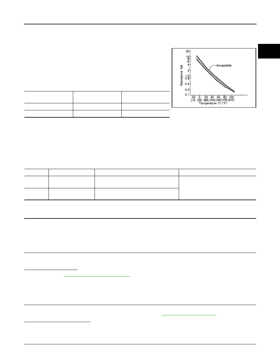
The fuel tank temperature sensor is used to detect the fuel tempera-

ture inside the fuel tank. The sensor modifies a voltage signal from

the ECM. The modified signal returns to the ECM as the fuel temper-

ature input. The sensor uses a thermistor which is sensitive to the

change in temperature. The electrical resistance of the thermistor

decreases as temperature increases.

<Reference data>

*: These data are reference values and are measured between ECM terminal 95 (Fuel tank temperature sensor) and ground.

CAUTION:

Do not use ECM ground terminals when measuring input/output voltage. Doing so may result in damage to the ECM's transis-
tor. Use a ground other than ECM terminals, such as the ground.

DTC Logic

INFOID:0000000004349302

DTC DETECTION LOGIC

DTC CONFIRMATION PROCEDURE

1.

PRECONDITIONING

If DTC Confirmation Procedure has been previously conducted, always turn ignition switch OFF and wait at

least 10 seconds before conducting the next test.

>> GO TO 2.

2.

PERFORM DTC CONFIRMATION PROCEDURE

1. Turn ignition switch ON and wait at least 5 seconds.

2. Check 1st trip DTC.
Is 1st trip DTC detected?

YES

>> Go to 

EC-265, "Diagnosis Procedure"

.

NO

>> INSPECTION END

Diagnosis Procedure

INFOID:0000000004349303

1.

CHECK GROUND CONNECTION

1. Turn ignition switch OFF.

2. Check ground connection E9. Refer to Ground Inspection in 

GI-45, "Circuit Inspection"

.

Is the inspection result normal?

YES

>> GO TO 2.

NO

>> Repair or replace ground connection.

2.

CHECK FUEL TANK TEMPERATURE SENSOR POWER SUPPLY CIRCUIT

Fluid temperature

°C (°F)]

Voltage*

(V)

Resistance

(k

20 (68)

3.5

2.3 - 2.7

50 (122)

2.2

0.79 - 0.90

SEF012P

DTC No.

Trouble diagnosis name

DTC detecting condition

Possible cause

P0182

Fuel tank temperature 
sensor circuit low input

An excessively low voltage from the sensor is 
sent to ECM.

• Harness or connectors

(The sensor circuit is open or shorted.)

• Fuel tank temperature sensor

P0183

Fuel tank temperature 
sensor circuit high input

An excessively high voltage from the sensor is 
sent to ECM.

EC-266

< COMPONENT DIAGNOSIS >

[QR25DE FOR CALIFORNIA]

P0182, P0183 FTT SENSOR

1. Turn ignition switch OFF.

2. Disconnect “fuel level sensor unit and fuel pump” harness connector.

3. Turn ignition switch ON.

4. Check the voltage between “fuel level sensor unit and fuel

pump” harness connector and ground.

Is the inspection result normal?

YES

>> GO TO 4.

NO

>> GO TO 3.

3.

DETECT MALFUNCTIONING PART

Check the following.

• Harness connectors E29, B10

• Harness for open or short between ECM and “fuel level sensor unit and fuel pump”

>> Repair open circuit or short to ground or short to power in harness or connector.

4.

CHECK FUEL TANK TEMPERATURE SENSOR GROUND CIRCUIT FOR OPEN AND SHORT

1. Turn ignition switch OFF.

2. Check the continuity between “fuel level sensor unit and fuel pump” harness connector and ECM harness

connector.

3. Also check harness for short to ground and short to power.
Is the inspection result normal?

YES

>> GO TO 6.

NO

>> GO TO 5.

5.

DETECT MALFUNCTIONING PART

Check the following.

• Harness connectors B1, M6

• Harness connectors E30, M1

• Harness for open or short between “fuel level sensor unit and fuel pump” and ECM

>> Repair open circuit or short to ground or short to power in harness or connector.

6.

CHECK FUEL TANK TEMPERATURE SENSOR

Refer to 

EC-264, "Component Inspection"

.

Is the inspection result normal?

YES

>> GO TO 7.

NO

>> Replace “fuel level sensor unit and fuel pump”.

7.

CHECK INTERMITTENT INCIDENT

Refer to 

GI-42, "Intermittent Incident"

.

>> INSPECTION END

Fuel level sensor unit and fuel pump

Ground

Voltage

Connector

Terminal

B42

4

Ground Approx. 5 V

PBIB0932E

Fuel level sensor unit and fuel pump

ECM

Continuity

Connector

Terminal

Connector Terminal

B42

5

E10

104

Existed

P0182, P0183 FTT SENSOR

EC-267

< COMPONENT DIAGNOSIS >

[QR25DE FOR CALIFORNIA]

C

D

E

F

G

H

I

J

K

L

M

A

EC

N

P

O

Component Inspection

INFOID:0000000004349304

1.

CHECK FUEL TANK TEMPERATURE SENSOR

1. Turn ignition switch OFF.

2. Disconnect “fuel level sensor unit and fuel pump” harness connector.

3. Remove fuel level sensor unit.

4. Check resistance between “fuel level sensor unit and fuel pump”

terminals by heating with hot water as shown in the figure.

Is the inspection result normal?

YES

>> INSPECTION END

NO

>> Replace “fuel level sensor unit and fuel pump”.

Terminals

Condition

Resistance

4 and 5

Temperature 

°C (°F)

20 (68)

2.3 - 2.7 k

50 (122)

0.79 - 0.90 k

PBIB0931E

EC-268

< COMPONENT DIAGNOSIS >

[QR25DE FOR CALIFORNIA]

P0222, P0223 TP SENSOR

P0222, P0223 TP SENSOR

Description

INFOID:0000000004455875

Electric throttle control actuator consists of throttle control motor,

throttle position sensor, etc. The throttle position sensor responds to

the throttle valve movement. 

The throttle position sensor has two sensors. These sensors are a

kind of potentiometers which transform the throttle valve position into

output voltage, and emit the voltage signal to the ECM. In addition,

these sensors detect the opening and closing speed of the throttle

valve and feed the voltage signals to the ECM. The ECM judges the

current opening angle of the throttle valve from these signals and the

ECM controls the throttle control motor to make the throttle valve

opening angle properly in response to driving condition.

DTC Logic

INFOID:0000000004349306

DTC DETECTION LOGIC

DTC CONFIRMATION PROCEDURE

1.

PRECONDITIONING

If DTC Confirmation Procedure has been previously conducted, always turn ignition switch OFF and wait at

least 10 seconds before conducting the next test.

TESTING CONDITION:

Before performing the following procedure, confirm that battery voltage is more than 8V at idle.

>> GO TO 2.

2.

PERFORM DTC CONFIRMATION PROCEDURE

1. Start engine and let it idle for 1 second.

2. Check DTC.
Is DTC detected?

YES

>> Go to 

EC-268, "Diagnosis Procedure"

.

NO

>> INSPECTION END

Diagnosis Procedure

INFOID:0000000004349307

1.

CHECK GROUND CONNECTION

1. Turn ignition switch OFF.

2. Check ground connection E9. Refer to Ground Inspection in 

GI-45, "Circuit Inspection"

.

Is the inspection result normal?

YES

>> GO TO 2.

NO

>> Repair or replace ground connection.

2.

CHECK THROTTLE POSITION SENSOR 1 POWER SUPPLY CIRCUIT

1. Disconnect electric throttle control actuator harness connector.

2. Turn ignition switch ON.

PBIB0145E

DTC No.

Trouble diagnosis name

DTC detecting condition

Possible cause

P0222

Throttle position sensor 
1 circuit low input

An excessively low voltage from the TP sensor 
1 is sent to ECM.

• Harness or connectors

(TP sensor 1 circuit is open or shorted.)

• Electric throttle control actuator

(TP sensor 1)

P0223

Throttle position sensor 
1 circuit high input

An excessively high voltage from the TP sensor 
1 is sent to ECM.


Content   ..  284  285  286  287   ..