Content .. 1553 1554 1555 1556 ..
Nissan Altima L32. Manual - part 1555
WCS-86
< ECU DIAGNOSIS >
BCM (BODY CONTROL MODULE)
65
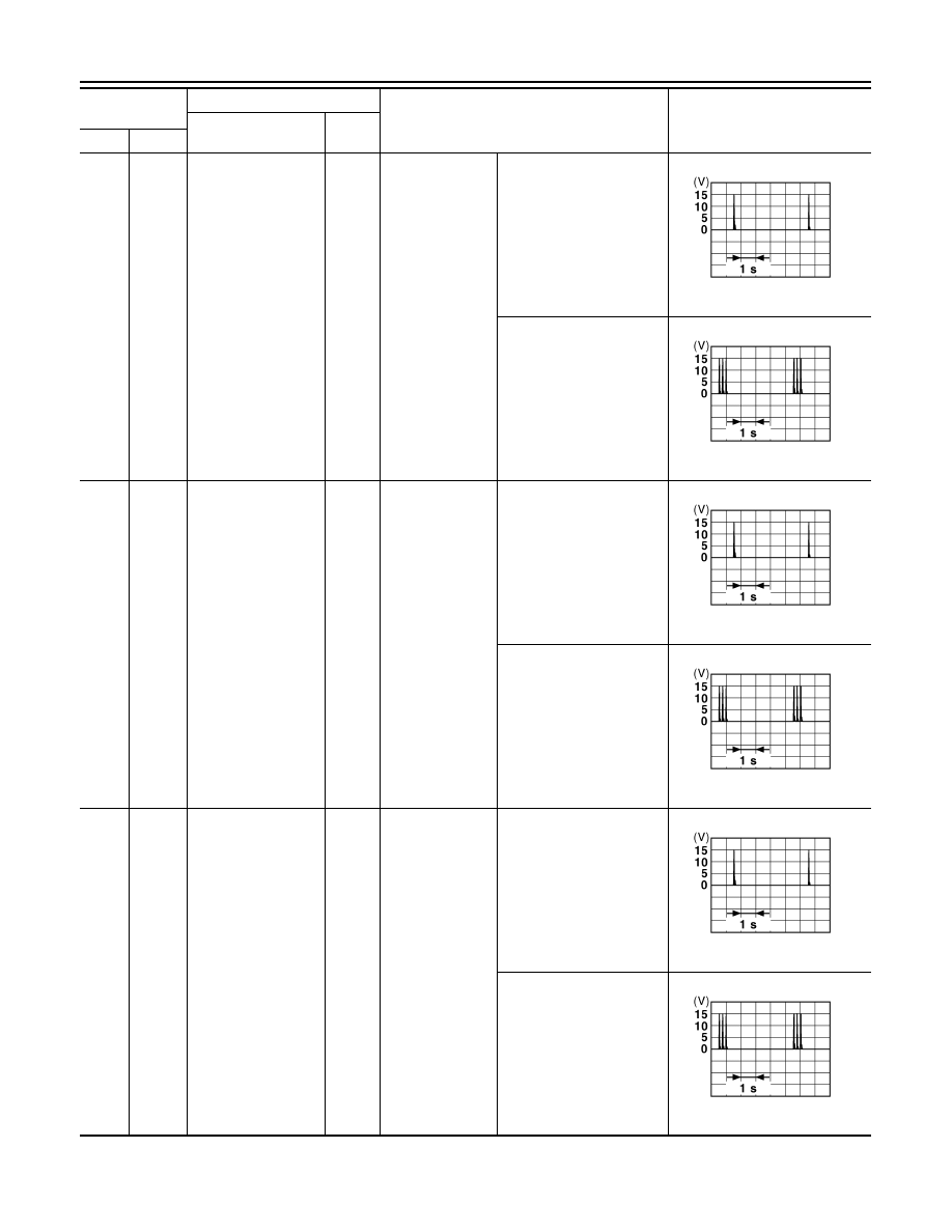
4
(P)
Ground
Front outside handle
LH antenna (+)
Output
When the front
door LH request
switch is operat-
ed with ignition
switch OFF
When Intelligent Key is in
the antenna detection area
When Intelligent Key is not
in the antenna detection
area
66
(R)
Ground
Instrument panel an-
tenna (-)
Output
Ignition switch
OFF
When Intelligent Key is in
the passenger compart-
ment
When Intelligent Key is not
in the passenger compart-
ment
67
(G)
Ground
Instrument panel an-
tenna (+)
Output
Ignition switch
OFF
When Intelligent Key is in
the passenger compart-
ment
When Intelligent Key is not
in the passenger compart-
ment
Terminal No.
(Wire color)
Description
Condition
Value
(Approx.)
Signal name
Input/
Output
(+)
(-)
JMKIA0062GB
JMKIA0063GB
JMKIA0062GB
JMKIA0063GB
JMKIA0062GB
JMKIA0063GB