Content .. 1505 1506 1507 1508 ..
Nissan Altima L32. Manual - part 1507
TM-372
< COMPONENT DIAGNOSIS >
[CVT: RE0F10A]
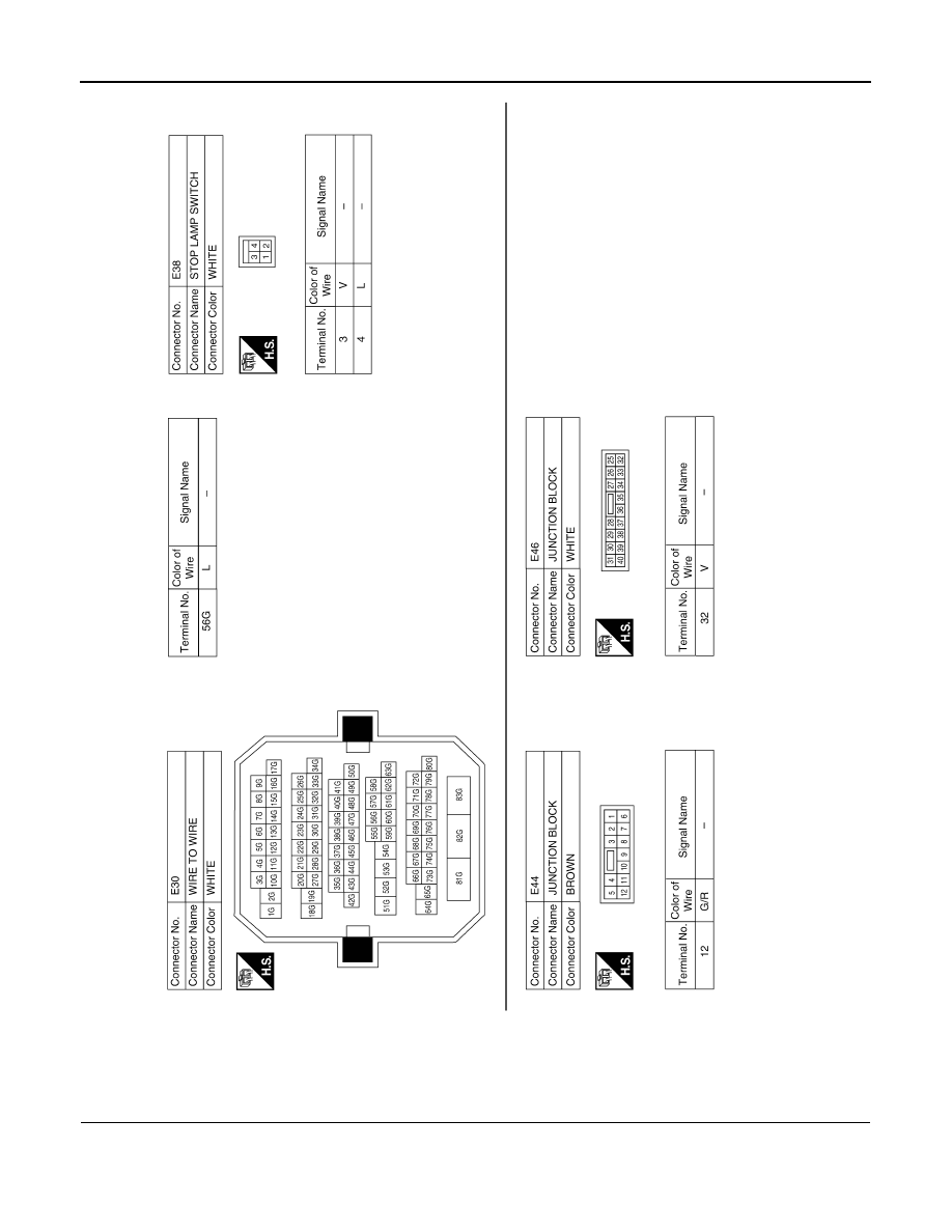
SHIFT LOCK SYSTEM
Diagnosis Procedure
INFOID:0000000004494648
1.
CHECK POWER SOURCE
ABDIA0186GB
|
|
|
Content .. 1505 1506 1507 1508 ..
TM-372 < COMPONENT DIAGNOSIS > [CVT: RE0F10A] SHIFT LOCK SYSTEM Diagnosis Procedure INFOID:0000000004494648 1. CHECK POWER SOURCE ABDIA0186GB |