Nissan Altima L32. Manual - part 1433


  Index      Nissan     Nissan Altima L32 (2007-2009 year) - Service and Repair Manual


Search            


Content   ..  1431  1432  1433  1434   ..


Nissan Altima L32. Manual - part 1433


TM-76

< DISASSEMBLY AND ASSEMBLY >

[6MT: RS6F52A]

FINAL DRIVE

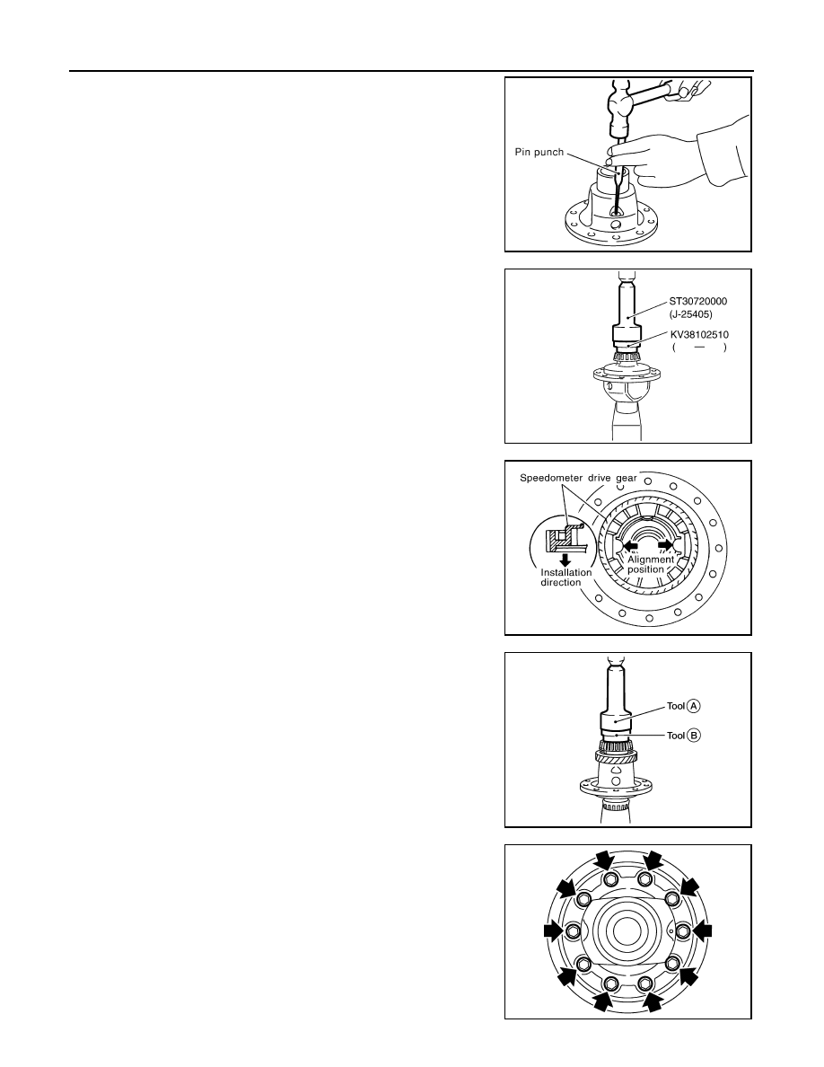
6. Install retaining pin into pinion mate shaft using suitable tool.

CAUTION:

Do not reuse retaining pin.

7. Press in differential side bearing (transaxle case side) to differ-

ential case using Tools.

CAUTION:

Replace differential side bearing and differential side bear-

ing outer race as a set.

8. Align and install speedometer drive gear onto differential case.

9. Press in differential side bearing (clutch housing side) to differ-

ential case using Tools (A) and (B).

CAUTION:

• Do not reuse differential side bearing and differential side

bearing outer race.

• Replace differential side bearing and differential side

bearing outer race as a set.

10. Install final gear into differential case and tighten final gear bolts

to the specified torque.

SCIA0908E

Tool numbers

: ST30720000 (J-25405)
: KV38102510 ( — )

PCIB0952E

SMT842D

Tool numbers

A: ST30720000 (J-25405)
B: KV38102510 ( — )

WCIA0305E

SCIA0912E

FINAL DRIVE

TM-77

< DISASSEMBLY AND ASSEMBLY >

[6MT: RS6F52A]

C

E

F

G

H

I

J

K

L

M

A

B

TM

N

O

P

Inspection

INFOID:0000000004201614

INSPECTION BEFORE DISASSEMBLY

• Check the clearance between side gear and differential case as follows.
1. Clean final drive assembly sufficiently to prevent side gear thrust washer, differential case, side gear, and

other parts from sticking by gear oil.

2. Put differential case vertically so that side gear to be measured faces upward.
3. Place Tool and a dial indicator onto side gear.

4. Move side gear up and down, and measure the clearance.

CAUTION:

There should be no resistance and gears should rotate

freely.

5. If not within specification, adjust the clearance by changing side

gear thrust washer thickness.

6. Turn differential case upside down and measure the clearance between side gear and differential case on

the other side in the same way.

INSPECTION AFTER DISASSEMBLY

Gear, Washer, Shaft, And Case

• Check side gears, side gear thrust washers, pinion mate shaft, pin-

ion mate gears, pinion mate thrust washers and differential case. If

necessary, replace with a new one.

Bearing

Tool number

:  —  (J-39713)

PCIB0950E

Allowable Clearance be-
tween side gear and dif-
ferential case with thrust 
washer

: Refer to 

TM-84, "Differential 

Side Gear Clearance"

.

SMT611A

MTK0135D

TM-78

< DISASSEMBLY AND ASSEMBLY >

[6MT: RS6F52A]

FINAL DRIVE

• Check for bearing damage and rough rotation. If necessary,

replace with a new one.

CAUTION:

When replacing tapered roller bearing, replace outer and inner

races as a set.

SPD715

SHIFT FORK AND FORK ROD

TM-79

< DISASSEMBLY AND ASSEMBLY >

[6MT: RS6F52A]

C

E

F

G

H

I

J

K

L

M

A

B

TM

N

O

P

SHIFT FORK AND FORK ROD

Exploded View

INFOID:0000000004201615

Refer to 

TM-28, "Exploded View"

.

Disassembly

INFOID:0000000004201616

1. Remove return spring to striking rod assembly.

Assembly

INFOID:0000000004201617

1. Temporarily install return spring to striking rod assembly.

CAUTION:

Be careful with the orientation of return spring.

2. Attach one end of the return spring to striking interlock of striking

rod assembly while holding return spring.

CAUTION:

• When installing, check that return spring is securely

seated in the groove of striking interlock of striking rod

assembly.

PCIB1867E

PCIB1830E

PCIB1831E

PCIB1833E


Content   ..  1431  1432  1433  1434   ..