Content .. 1398 1399 1400 1401 ..
Nissan Altima L32. Manual - part 1400
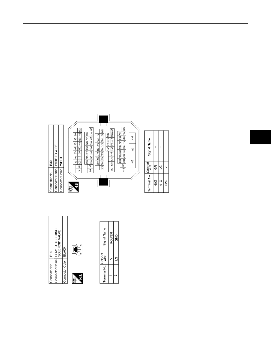
POWER STEERING CONTROL UNIT
STC-19
< ECU DIAGNOSIS >
C
D
E
F
H
I
J
K
L
M
A
B
STC
N
O
P
Fail Safe
INFOID:0000000004205838
EPS system
ABGIA0012GB
|
|
|
Content .. 1398 1399 1400 1401 ..
POWER STEERING CONTROL UNIT STC-19 < ECU DIAGNOSIS > C D E F H I J K L M A B STC N O P Fail Safe INFOID:0000000004205838 EPS system ABGIA0012GB |