Content .. 1334 1335 1336 1337 ..
Nissan Altima L32. Manual - part 1336
SEC-494
< COMPONENT DIAGNOSIS >
[SEDAN WITHOUT INTELLIGENT KEY]
B2612 STEERING STATUS
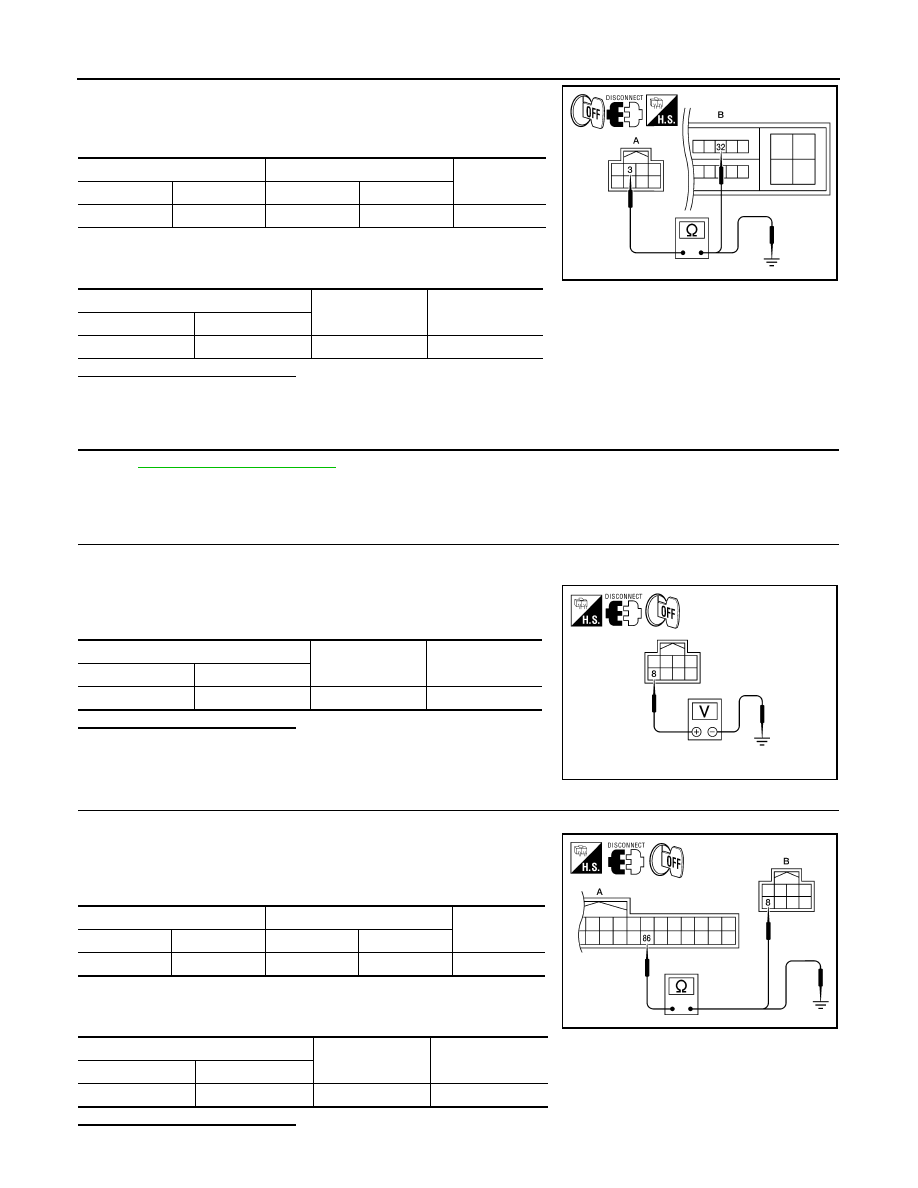
1. Check continuity between electronic steering column lock har-
ness connector M32 (A) terminal 3 and IPDM E/R harness con-
nector E18 (B) terminal 32.
2. Check continuity between electronic steering column lock har-
ness connector M32 (A) terminal 3 and ground.
Is the inspection result normal?
YES
>> GO TO 6
NO
>> Repair harness or connector.
6.
CHECK INTERMITTENT INCIDENT
GI-42, "Intermittent Incident"
>> Inspection End.
7.
CHECK BCM OUTPUT SIGNAL
1. Turn ignition switch OFF.
2. Disconnect electronic steering column lock harness connector and IPDM E/R harness connector.
3. Check voltage between electronic steering column lock harness
connector and ground.
Is the inspection result normal?
YES
>> GO TO 9
NO
>> GO TO 8
8.
CHECK ELECTRONIC STEERING COLUMN LOCK CIRCUIT-I
1. Disconnect BCM harness connector.
2. Check continuity between BCM harness connector M19 (A) ter-
minal 86 and electronic steering column lock harness connector
M32 (B) terminal 8.
3. Check continuity between BCM harness connector M19 (A) ter-
minal 86 and ground.
Is the inspection result normal?
Electronic steering column lock
IPDM E/R
Continuity
Connector
Terminal
Connector
Terminal
A: M32
3
B: E18
32
Yes
Electronic steering column lock
Ground
Continuity
Connector
Terminal
A: M32
3
Ground
No
ALKIA0456ZZ
Electronic steering column lock
Ground
Voltage [V]
Connector
Terminal
M32
8
Ground
Battery voltage
ALKIA0457ZZ
BCM
Electronic steering column lock
Continuity
Connector
Terminal
Connector
Terminal
A: M19
86
B: M32
8
Yes
BCM
Ground
Continuity
Connector
Terminal
A: M19
86
Ground
No
ALKIA0458ZZ