Nissan Altima L32. Manual - part 1191


  Index      Nissan     Nissan Altima L32 (2007-2009 year) - Service and Repair Manual


Search            


Content   ..  1189  1190  1191  1192   ..


Nissan Altima L32. Manual - part 1191


REAR SUSPENSION ASSEMBLY

RSU-9

< ON-VEHICLE MAINTENANCE >

C

D

F

G

H

I

J

K

L

M

A

B

RSU

N

O

P

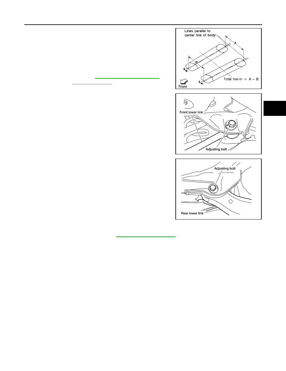
4. Measure distance (A) from rear side.
5. Push the vehicle slowly ahead to rotate the wheels 180

°

degrees (1/2 a turn).

• If the wheels have rotated more than 180

° degrees (1/2 a

turn), try the above procedure again from the beginning. Never

push vehicle backward.

6. Measure distance (B) from front side.

7. Adjust toe-in by turning adjusting bolts.

NOTE:

Toe changes about 1.5 mm (0.059 in) [One side] with each grad-

uation of the adjusting bolt. 

8. Tighten the adjusting bolt nuts to the specified torque.

Total toe-in : Refer to 

RSU-18, "Rear Wheel Align-

ment (Unladen*)"

.

SFA234AC

LEIA0008E

LEIA0009E

Adjusting bolt nuts

: Refer to 

RSU-10, "Exploded View"

.

RSU-10

< REMOVAL AND INSTALLATION >

REAR SUSPENSION ASSEMBLY

REMOVAL AND INSTALLATION

REAR SUSPENSION ASSEMBLY

Exploded View

INFOID:0000000004205679

SEDAN

AWEIA0127GB

1.

Cap

2.

Shock absorber insulator

3.

Shock absorber seal

4.

Bound bumper

5.

Shock absorber

6.

Suspension arm

7.

Connecting rod mount bracket

8.

Connecting rod

9.

Upper rubber seat

10. Coil spring

11. Lower rubber seat

12. Knuckle

13. Knuckle bushing

14. Rear lower link

15. Suspension arm bushing

REAR SUSPENSION ASSEMBLY

RSU-11

< REMOVAL AND INSTALLATION >

C

D

F

G

H

I

J

K

L

M

A

B

RSU

N

O

P

COUPE

16. Front lower link

17. Radius arm

18. Front member stay (LH)

19. Front member stay (RH)

20. Stabilizer bar clamp

21. Bushing

22. Stabilizer bar

23. Member stopper

24. Rear suspension member

25. Rear member stay

26. Ball seat

Front

AWEIA0128GB

1.

Cap

2.

Shock absorber insulator

3.

Shock absorber seal

4.

Bound bumper

5.

Shock absorber

6.

Suspension arm

7.

Connecting rod mount bracket

8.

Connecting rod

9.

Upper rubber seat

10. Coil spring

11. Lower rubber seat

12. Knuckle

13. Knuckle bushing

14. Rear lower link

15. Suspension arm bushing

RSU-12

< REMOVAL AND INSTALLATION >

REAR SUSPENSION ASSEMBLY

Removal and Installation

INFOID:0000000004205680

Removal

CAUTION:

Before removing the rear suspension assembly, disconnect the ABS wheel sensor from the assembly.

Failure to do so may result in damage to the sensor wires and the sensor becoming inoperative.
1. Remove the center exhaust tube with muffler(s). Refer to 

EX-6, "Removal and Installation"

 (QR25DE) or

EX-12, "Removal and Installation"

 (VQ35DE).

2. Remove brake caliper assembly and reposition aside, without disconnecting the hydraulic hose, using

power tools. Refer to 

BR-35, "BRAKE CALIPER ASSEMBLY : Exploded View"

.

• Leave the brake hydraulic hose connected to the brake caliper.

• Do not depress the brake pedal, or the caliper piston will pop out.

• Do not pull or twist the brake hydraulic hose.

3. Remove brake rotor. Refer to 

BR-35, "BRAKE CALIPER ASSEMBLY : Exploded View"

.

4. Disconnect parking brake cable from knuckle. Refer to 

PB-6, "PEDAL TYPE : Exploded View"

 (pedal

type), 

PB-7, "LEVER TYPE : Exploded View"

 (lever type).

5. Remove rear wheel sensors. Refer to 

BRC-63, "Removal and Installation"

 (ABS)

BRC-134, "Removal

and Installation"

 (TCS/ABS), 

BRC-236, "Removal and Installation"

 (VDC/TCS/ABS).

6. Remove lower shock absorber nuts using power tools.
7. Remove lower control arm link adjusting bolt and arm. Refer to 

RSU-13, "Removal and Installation"

.

8. Remove upper ball joint nut and cotter pin. Refer to 

RSU-10, "Exploded View"

.

9. Disconnect radius rod member side. Refer to 

RSU-15, "Removal and Installation"

.

10. Disconnect lower link adjusting bolt. Refer to 

RSU-14, "Removal and Installation"

.

11. Remove knuckle. Refer to 

RSU-10, "Exploded View"

.

12. Remove stabilizer bar. Refer to 

RSU-16, "Removal and Installation"

.

13. Disconnect lower link adjusting bolt. Refer to 

RSU-14, "Removal and Installation"

.

14. Disconnect member harness.
15. Support the rear suspension assembly using a suitable jack.
16. Remove the suspension member nuts and member stay bolts using power tools.
17. Lower the rear suspension assembly.

Installation

Installation is in the reverse order of removal.

• Check the rear wheel alignment and adjust if necessary. Refer to 

RSU-18, "Rear Wheel Alignment

(Unladen*)"

.

16. Front lower link

17. Radius arm

18. Front member stay (LH)

19. Front member stay (RH)

20. Stabilizer bar clamp

21. Bushing

22. Stabilizer bar

23. Member stopper

24. Rear suspension member

25. Rear member stay

26. Ball seat

Front


Content   ..  1189  1190  1191  1192   ..