Content .. 1166 1167 1168 1169 ..
Nissan Altima L32. Manual - part 1168
RF-14
< COMPONENT DIAGNOSIS >
POWER SUPPLY AND GROUND CIRCUIT
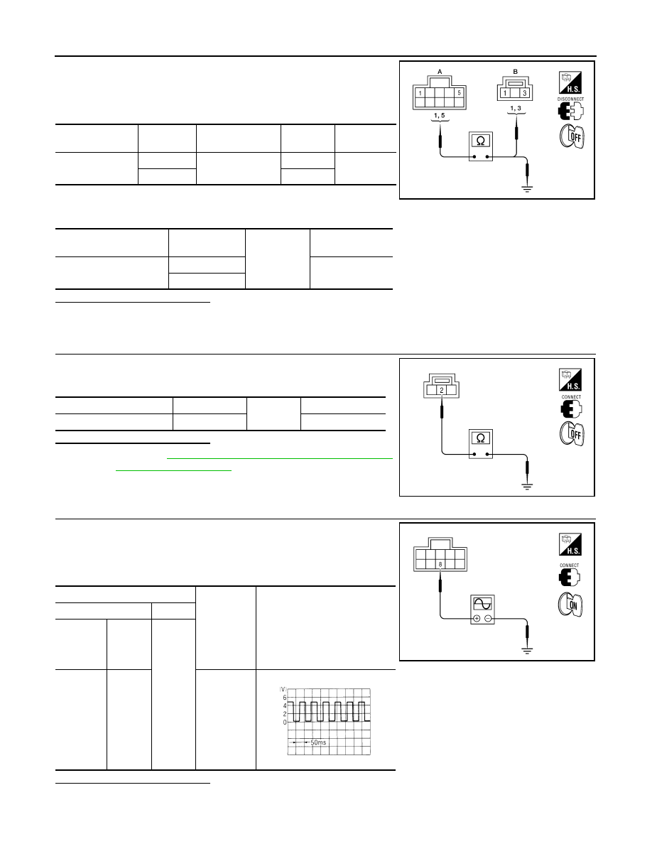
1. Turn ignition switch OFF.
2. Disconnect sunroof motor assembly and sunroof switch.
3. Check continuity between sunroof motor assembly connector
(A) and sunroof switch connector (B).
4. Check continuity between sunroof motor assembly connector
(A) and ground.
Is the inspection result normal?
YES
>> GO TO 7
NO
>> Repair or replace harness.
7.
CHECK SUNROOF SWITCH GROUND CIRCUIT
1. Connect sunroof motor assembly.
2. Check continuity between sunroof switch connector and ground.
Is the inspection result normal?
YES
>> Refer to
RF-15, "SUNROOF MOTOR ASSEMBLY :
NO
>> Repair or replace harness.
8.
CHECK COMBINATION METER SIGNAL
1. Connect sunroof motor assembly.
2. Turn ignition switch ON.
3. Check signal between sunroof motor assembly connector and
ground with oscilloscope.
Is the inspection result normal?
Sunroof motor as-
sembly connector
Terminal
Sunroof switch
connector
Terminal
Continuity
R5 (A)
5
R6 (B)
1
Yes
1
3
Sunroof motor assembly
connector
Terminal
Ground
Continuity
R5 (A)
5
No
1
ALKIA0264ZZ
Sunroof switch connector
Terminal
Ground
Continuity
R6
2
Yes
ALKIA0265ZZ
Terminals
Condition
Signal
(Reference value)
(+)
(-)
Sunroof
motor as-
sembly
connector
Terminal
Ground
R5
8
Speed meter
operated
[When vehi-
cle speed is
ap-
prox.40km/h
(25MPH)]
ALKIA0266ZZ
ELF1080D