Nissan Terrano model r20 series 2004. Manual - part 398


  Index      Nissan     Nissan Terrano model r20 series 2004 - Service and Repair Manual


Search            


Content   ..  396  397  398  399   ..


Nissan Terrano model r20 series 2004. Manual - part 398


INSPECTION/REVOLUTION SIGNAL

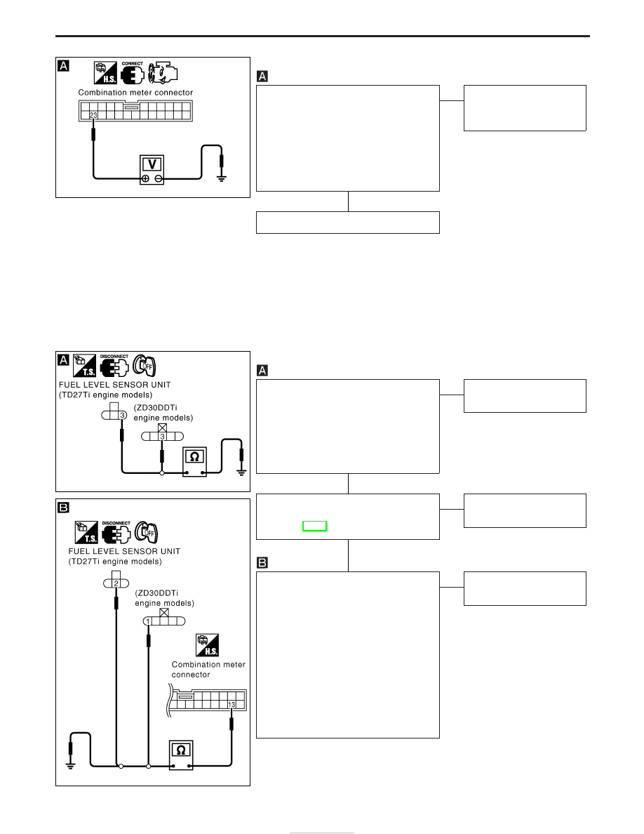
CHECK ECM OUTPUT SIGNAL.
1. Start engine.
2. Check voltage between combination

meter terminal 23 and ground at idle
and 2,000 rpm.

Higher rpm = Higher voltage
Lower rpm = Lower voltage
Voltage should change with rpm.

OK

E

NG

Check harness for open or
short between ECM and
meter.

Engine revolution signal is OK.

INSPECTION/FUEL LEVEL SENSOR UNIT

CHECK GROUND CIRCUIT FOR FUEL
LEVEL SENSOR UNIT.
1. Disconnect fuel level sensor unit har-

ness connector.

2. Check continuity between fuel level

sensor unit terminal 3 and ground.

Continuity should exist.

OK

E

NG

Repair harness or connec-
tor.

CHECK FUEL LEVEL SENSOR UNIT.
Refer to “FUEL LEVEL SENSOR UNIT
CHECK” (EL-98).

OK

E

NG

Replace fuel level sensor
unit.

CHECK HARNESS FOR OPEN OR
SHORT.
1. Disconnect fuel level sensor unit har-

ness connector and combination meter
harness connector.

2. Check continuity between combination

meter terminal 13 and fuel level sensor
unit terminal 2 (TD27Ti engine) or 1
(ZD30DDTi engine).

Continuity should exist.
3. Check continuity between combination

meter terminal 13 and ground.

Continuity should not exist.

E

NG

Repair harness or connec-
tor.

YEL881E

YEL882E

YEL883E

H

H

H

METER AND GAUGES

Trouble Diagnoses (Cont’d)

EL-96

INSPECTION/THERMAL TRANSMITTER

CHECK THERMAL TRANSMITTER.
Refer to “THERMAL TRANSMITTER
CHECK” (EL-98).

OK

E

NG

Replace thermal transmit-
ter.

CHECK HARNESS FOR OPEN OR
SHORT.
1. Disconnect combination meter connec-

tor and thermal transmitter connector.

2. Check continuity between combination

meter terminal 19 and thermal transmit-
ter terminal 1.

Continuity should exist.
3. Check continuity between combination

meter terminal 19 and ground.

Continuity should not exist.

OK

E

NG

Repair harness or connec-
tor.

Thermal transmitter is OK.

Components Inspection

AMBIENT TEMPERATURE SENSOR

<Reference data>

Intake air temperature

°C (°F)

Resistance

k

−20 (−4)

10.5 - 10.8

0 (32)

6.1 - 6.24

20 (68)

3.0 - 3.1

50 (122)

0.85 - 1.04

YEL884E

SEF012P

H

H

METER AND GAUGES

Trouble Diagnoses (Cont’d)

EL-97

Fuel Level Sensor Unit Check

I

For removal, refer to FE section.

Check the resistance between terminals (G) and (E).

Ohmmeter

Float position mm (in)

Resis-

tance
value

(

)

(+)

(−)

TD27Ti

ZD30DDTi

Hardtop

models

Wagon

models

Hardtop

models

Wagon

models

G

E

*3

Full

36 (1.42) 25 (0.98) 37 (1.46) 27 (1.06)

Approx.

7

2

1/2

159

(6.26)

120

(4.72)

160

(6.30)

120

(4.72)

96 - 108

*1

Emp-

ty

286

(11.26)

218

(8.58)

282

(11.10)

220

(8.66)

280 -

290

Values *1 and *3: with the dipstick float at its lower or upper limit.

Thermal Transmitter Check

Check the resistance between the terminals of thermal transmitter
and body ground.

Water temperature

Resistance

65°C (149°F)

Approx. 951 - 1,109

91°C (196°F)

Approx. 431 - 510

VEHICLE SPEED SENSOR SIGNAL CHECK

1. Remove vehicle speed sensor from transmission.
2. Turn vehicle speed sensor pinion quickly and measure voltage

between terminals 2 and 3.

YEL297D

SEL233P

YEL880E

METER AND GAUGES

EL-98

Schematic

YEL762E

WARNING LAMPS AND CHIME

EL-99


Content   ..  396  397  398  399   ..