Nissan Terrano model r20 series 2004. Manual - part 242


  Index      Nissan     Nissan Terrano model r20 series 2004 - Service and Repair Manual


Search            


Content   ..  240  241  242  243   ..


Nissan Terrano model r20 series 2004. Manual - part 242


I

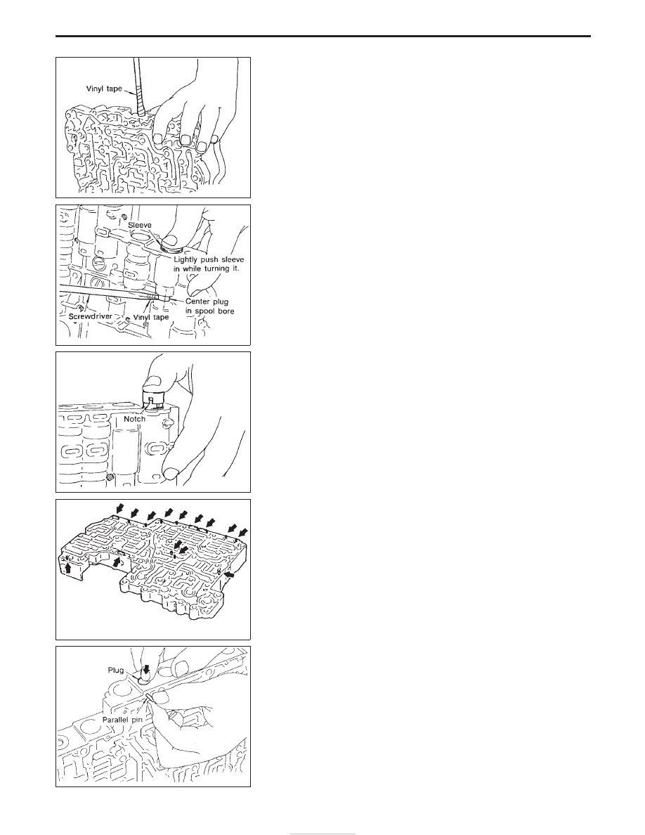
Wrap a small screwdriver with vinyl tape and use it to insert the
valves into proper position.

Pressure regulator valve

I

If pressure regulator plug is not centered properly, sleeve can-
not be inserted into bore in upper body.
If this happens, use vinyl tape wrapped screwdriver to center
sleeve until it can be inserted.

I

Turn sleeve slightly while installing.

Accumulator control plug

I

Align protrusion of accumulator control sleeve with notch in
plug.

I

Align parallel pin groove in plug with parallel pin, and install
accumulator control valve.

2. Install parallel pins and retainer plates.

I

While pushing plug, install parallel pin.

SAT831A

SAT832A

SAT833A

SAT834A

SAT823A

REPAIR FOR COMPONENT PARTS

Control Valve Upper Body (Cont’d)

AT-152

4-2 sequence valve and relay valve

I

Push 4-2 sequence valve and relay valve with wire wrapped in
vinyl tape to prevent scratching valve body. Install parallel pins.

I

Insert retainer plate while pushing spring.

SAT835A

SAT836A

REPAIR FOR COMPONENT PARTS

Control Valve Upper Body (Cont’d)

AT-153

Control Valve Lower Body

Apply ATF to all components before their installation.

Numbers preceding valve springs correspond with those shown in SDS on page AT-202.

SAT112GA

REPAIR FOR COMPONENT PARTS

AT-154

DISASSEMBLY

1. Remove valves at parallel pins.
2. Remove valves at retainer plates.

For removal procedures, refer to “DISASSEMBLY” of Control
Valve Upper Body.

INSPECTION

Valve springs

I

Check each valve spring for damage or deformation. Also mea-
sure free length and outer diameter.

Inspection standard:

Refer to SDS, AT-202.

I

Replace valve springs if deformed or fatigued.

Control valves

I

Check sliding surfaces of control valves, sleeves and plugs for
damage.

ASSEMBLY

I

Install control valves.
For installation procedures, refer to “ASSEMBLY” of Control
Valve Upper Body, AT-151.

SAT838A

SAT829A

SAT838A

REPAIR FOR COMPONENT PARTS

Control Valve Lower Body (Cont’d)

AT-155


Content   ..  240  241  242  243   ..