Nissan Terrano model r20 series 2004. Manual - part 166


  Index      Nissan     Nissan Terrano model r20 series 2004 - Service and Repair Manual


Search            


Content   ..  164  165  166  167   ..


Nissan Terrano model r20 series 2004. Manual - part 166


Diagnostic Procedure
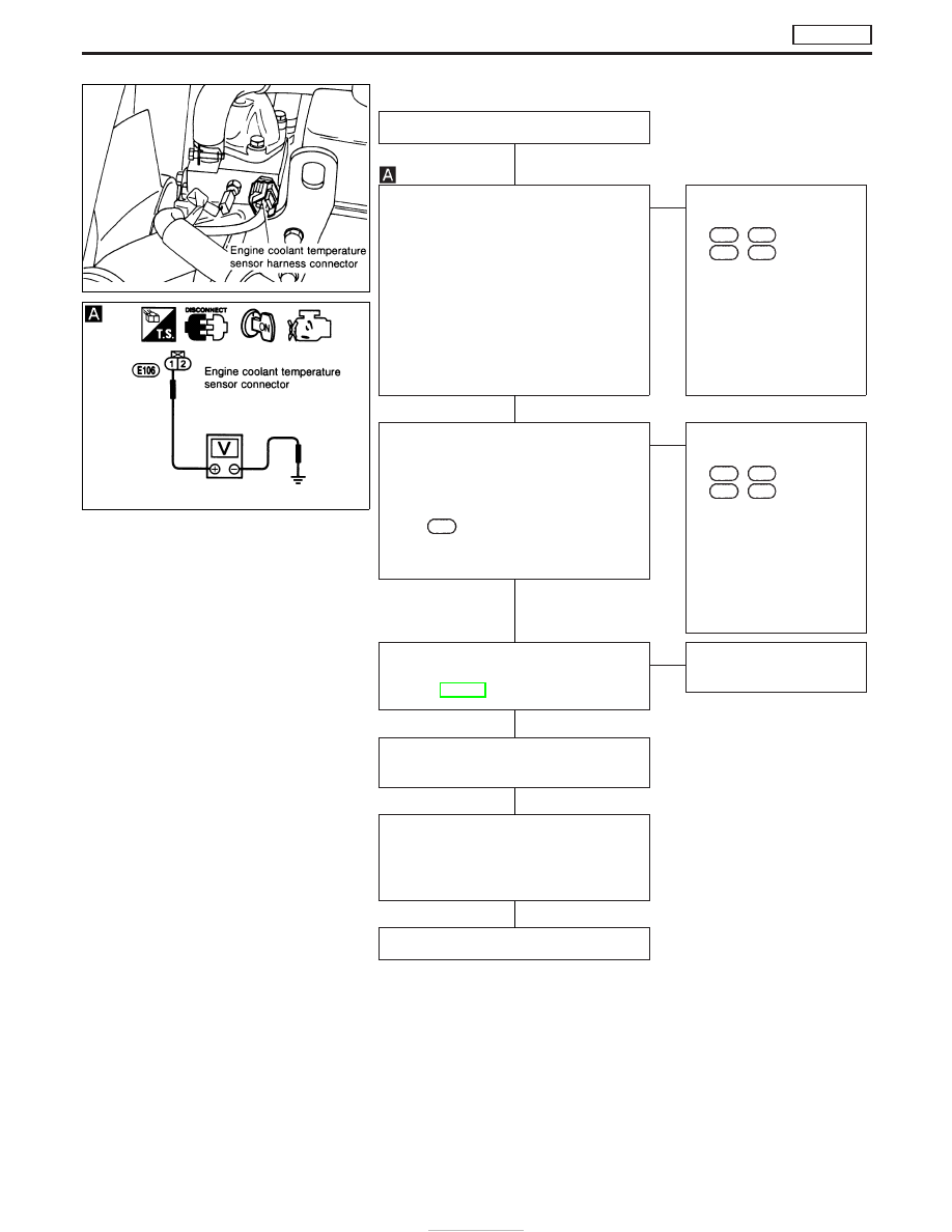
INSPECTION START

CHECK POWER SUPPLY.
1. Turn ignition switch to “LOCK” position.
2. Disconnect engine coolant temperature

sensor harness connector.

3. Turn ignition switch to “ON” position.
4. Check voltage between engine coolant

temperature sensor connector terminal

q

1

and engine ground with CONSULT-II

or tester.
Voltage:

Approximately 4.9V

OK

E

NG

Check the following:

I

Harness connectors

E151

,

F138

(LHD model)

E151

,

M843

(RHD

model)

I

Harness for open or
short circuit between
ECM and engine coolant
temperature sensor.

If NG, repair harness or
connectors.

CHECK GROUND CIRCUIT.
1. Turn ignition switch to “LOCK” position.
2. Check harness continuity between

engine coolant temperature sensor
connector terminal

q

2

and ECM termi-

nal

334

. Refer to wiring diagram.

Continuity should exist.
If OK, check harness for short-circuit.

OK

E

NG

Check the following:

I

Harness connectors

E151

,

F138

(LHD model)

E151

,

M843

(RHD

model)

I

Harness for open or
short circuit between
ECM and engine coolant
temperature sensor.

If NG, repair harness or
connectors.

CHECK COMPONENT
(Engine coolant temperature sensor).
Refer to EC-387.

OK

E

NG

Replace engine coolant
temperature sensor.

Disconnect and reconnect harness con-
nectors in the circuit. Then retest.

Trouble is not fixed.

Check ECM pin terminals for damage and
check the connection of ECM harness
connector. Reconnect ECM harness con-
nector and retest.

INSPECTION END

NEF487

NEF670

H

H

H

H

H

H

DTC P0115 COOLANT TEMP SEN

TD27Ti

EC-386

Component Inspection

ENGINE COOLANT TEMPERATURE SENSOR

Check resistance as shown in the figure.

Temperature °C (°F)

Resistance k

20 (68)

2.1 - 2.9

50 (122)

0.68 - 1.0

90 (194)

0.236 - 0.260

If NG, replace engine coolant temperature sensor.

SEF152P

SEF012P

DTC P0115 COOLANT TEMP SEN

TD27Ti

EC-387

Component Description

ACCELERATOR WORK UNIT

The accelerator position sensor is installed on the upper end of the
accelerator pedal assembly. The sensor detects the accelerator
position and sends a signal to the ECM. The ECM uses the signal
to determine the amount of fuel to be injected.
The accelerator position switch is installed inside the accelerator
position sensor. This switch is used for plausibility check of the
accelerator position sensor.

On Board Diagnosis Logic

DTC

Malfunction is detected when ...

Check Items

(Possible Cause)

P0120
0403

I

An excessively low or high voltage from the sensor is
detected by the ECM.

I

Harness or connectors
(The sensor or switch circuit is open or
short-circuited.)

I

Accelerator position sensor

I

Accelerator position switch

DTC Confirmation Procedure A (For General
Plausibility)

WITH CONSULT-II

1) Turn ignition switch to “ON” position.
2) Select “DATA MONITOR” mode with CONSULT-II.
3) Depress accelerator pedal fully and keep it for at least 1 sec-

ond. Then release it and wait at least 5 seconds.

WITHOUT CONSULT-II

1) Turn ignition switch to “ON” position.
2) Depress accelerator pedal fully and keep it for at least 1 sec-

ond. Then release it and wait at least 5 seconds.

3) Turn ignition switch to “LOCK” position, wait at least 5 seconds

and then turn to “ON” position.

4) Perform “Diagnostic Test Mode II (Self-diagnostic results)” with

ECM.

MEC959D

DTC P0120 ACCEL POS SENSOR

TD27Ti

EC-388

DTC Confirmation Procedure B (For
Accelerator Sticking)

If DTC P0571 is displayed same time, cure it at first.

WITH CONSULT-II

1) Turn ignition switch to “ON” position.
2) Select “DATA MONITOR” mode with CONSULT-II.
3) Start engine and rev it up to above 1,300 rpm.
4) Depress brake pedal immediately after releasing accelerator

pedal and keep it at least 5 seconds.

WITHOUT CONSULT-II

1) Start engine and rev it up to above 1,300 rpm.
2) Depress brake pedal immediately after releasing accelerator

pedal and keep it at least 5 seconds.

3) Turn ignition switch to “LOCK” position, wait at least 5 seconds

and then turn to “ON” position.

4) Perform “Diagnostic Test Mode II (Self-diagnostic results)” with

ECM.

DTC P0120 ACCEL POS SENSOR

TD27Ti

EC-389


Content   ..  164  165  166  167   ..