Nissan Titan A60. Manual - part 978
HEATER CORE
VTL-15
< REMOVAL AND INSTALLATION >
C
D
E
F
G
H
J
K
L
M
A
B
VTL
N
O
P
HEATER CORE
Removal and Installation
INFOID:0000000006161797
Heater and Cooling Unit Assembly
REMOVAL
1. Remove the heater and cooling unit assembly. Refer to
VTL-13, "Removal and Installation"
.
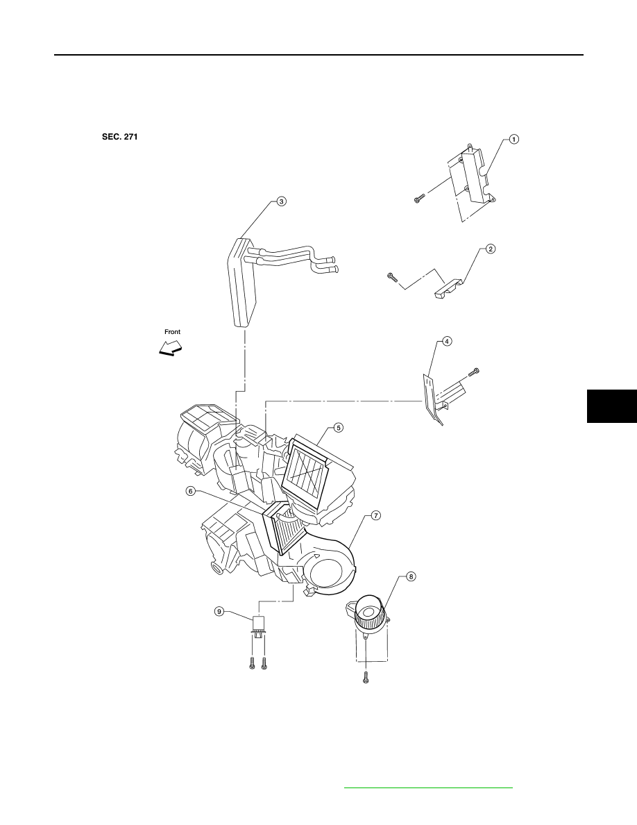
LJIA0138E
1.
Heater core cover
2.
Heater core pipe bracket
3.
Heater core
4.
Upper bracket
5.
Upper heater and cooling unit case
6.
A/C evaporator
7.
Lower heater and cooling unit case
8.
Blower motor
9.
Variable blower control or front blow-
er motor resistor if equipped