Nissan Titan A60. Manual - part 896


  Index      Nissan     Nissan Titan A60 (2011 year) - Service and Repair Manual


Search            


Content   ..  894  895  896  897   ..


Nissan Titan A60. Manual - part 896


HYDRAULIC LINE

ST-21

< UNIT REMOVAL AND INSTALLATION >

C

D

E

F

H

I

J

K

L

M

A

B

ST

N

O

P

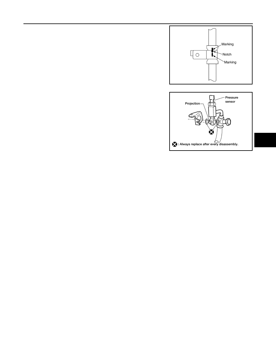
• Confirm mating marks are aligned with hose and clamp, then cor-

rect if needed.

• To install eye joint, align projection of eye joint with notch of power

steering pump, and attach eye joint to power steering oil pump

properly. Tighten eye bolt by hand fully, then torque to specifica-

tion.

SGIA0563E

WGIA0089E

ST-22

< UNIT DISASSEMBLY AND ASSEMBLY >

STEERING COLUMN

UNIT DISASSEMBLY AND ASSEMBLY

STEERING COLUMN

Disassembly and Assembly

INFOID:0000000006164507

Column Shift Model

CAUTION:

• Any time the ignition switch has been disconnected, removed or installed, the keys must be re-regis-

tered in the BCM. Refer to Consult-III operations IVIS/NVIS.

• Care must be taken not to give axial impact to steering column assembly during removal and instal-

lation.

• Care must be taken not to move power steering gear during removal of steering column assembly.

WGIA0085E

1.

Steering column assembly

2. Ignition switch

3.

Upper joint

4.

Spring

5. Tilt lever knob

6.

Self-shear screw

STEERING COLUMN

ST-23

< UNIT DISASSEMBLY AND ASSEMBLY >

C

D

E

F

H

I

J

K

L

M

A

B

ST

N

O

P

Floor Shift Model

CAUTION:

• Any time the ignition switch has been disconnected, removed or installed, the keys must be re-regis-

tered in the BCM. Refer to Consult-III operations IVIS/NVIS.

• Care must be taken not to give axial impact to steering column assembly during removal and instal-

lation.

• Care must be taken not to move power steering gear during removal of steering column assembly.

DISASSEMBLY

1. Remove spring from steering column assembly and tilt lever.
2. Remove upper joint bolt, then remove upper joint from steering column assembly.
3. Remove ignition switch tamper resistant self-shear type screws with a drill or other appropriate tool.

ASSEMBLY

• Assembly is in the reverse order of disassembly.

• Install new tamper resistant self-shear type screws.

• Any time the ignition switch has been disconnected, removed or

installed, the keys must be re-registered in the BCM. Refer to Con-

sult-III operations IVIS/NVIS.

INSPECTION AFTER ASSEMBLY

WGIA0088E

1.

Steering column assembly

2. Ignition switch

3.

Upper joint

4.

Spring

5. Tilt lever knob

6.

Self-shear screw

WGIA0009E

ST-24

< UNIT DISASSEMBLY AND ASSEMBLY >

STEERING COLUMN

When the steering wheel does not turn smoothly, check the steering column as follows:
1. Check the column bearings for damage or unevenness. Lubricate with recommended multi-purpose

grease. Replace the steering column as an assembly, if necessary.

2. Check the column tube for deformation or breakage. Replace the steering column as an assembly, if nec-

essary.

3. If the vehicle has been involved in a collision, or if noise and rattles are heard during a turn, check the

length (L) of the column. If out of specification, replace the steering column as an assembly.

4. Check for proper lubrication, apply grease as necessary.
5. Check for wear around the seal edges, replace as necessary.
6. Check for corrosion or pitting around the seal sliding area.
7. Replace the seal and shaft in case of seal edge wear or damage.
8. After installing the steering column, check the tilt mechanism for proper operation.

Steering column length L
L

: Refer to 

ST-30, "Steering Column"

L

1

: Refer to 

ST-30, "Steering Column"

L

2

: Refer to 

ST-30, "Steering Column"

WGIA0080E

SGIA0475E

Range (A)

: Refer to 

ST-30, "Steering Column"

WGIA0083E


Content   ..  894  895  896  897   ..