Nissan Titan A60. Manual - part 810


  Index      Nissan     Nissan Titan A60 (2011 year) - Service and Repair Manual


Search            


Content   ..  808  809  810  811   ..


Nissan Titan A60. Manual - part 810


SUNROOF SYSTEM

RF-7

< SYSTEM DESCRIPTION >

C

D

E

F

G

H

I

J

L

M

A

B

RF

N

O

P

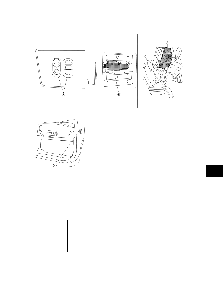
Component Parts Location

INFOID:0000000006163221

Component Description

INFOID:0000000006163222

ALKIA0867ZZ

1.

Sunroof switch R104

2.

Sunroof motor assembly R4 

3.

BCM  M18, M19, M20
(View with instrument panel re-
moved)

4.

Front door switch LH B8, RH B108

Component

Function

BCM

Supplies power to the sunroof motor assembly.

Sunroof switch

Transmits tilt up/down & slide open/close operation signal to sunroof motor assembly.

Sunroof motor assembly

The sunroof motor and integrated CPU enables tilt up/down & slide open/close as requested by 
the sunroof switch.

Front door switch

Detects door open/close condition and transmits to BCM.

RF-8

< SYSTEM DESCRIPTION >

DIAGNOSIS SYSTEM (BCM)

DIAGNOSIS SYSTEM (BCM)

COMMON ITEM
COMMON ITEM : CONSULT-III Function (BCM - COMMON ITEM)

INFOID:0000000006596468

APPLICATION ITEM

CONSULT-III performs the following functions via CAN communication with BCM.

SYSTEM APPLICATION

BCM can perform the following functions.

RETAINED PWR

Direct Diagnostic Mode

Description

Ecu Identification

The BCM part number is displayed.

Self Diagnostic Result

The BCM self diagnostic results are displayed.

Data Monitor

The BCM input/output data is displayed in real time.

Active Test

The BCM activates outputs to test components.

Work support

The settings for BCM functions can be changed.

Configuration

• The vehicle specification can be read and saved.
• The vehicle specification can be written when replacing BCM.

CAN Diag Support Mntr

The result of transmit/receive diagnosis of CAN communication is displayed.

System

Sub System

Direct Diagnostic Mode

E

cu

 Id

en

tifi

ca

tio

n

Se

lf Di

ag

no

st

ic Re

su

lt

Da

ta

 Mo

ni

tor

A

cti

ve

 T

est

W

o

rk support

Co

nf

igu

rat

ion

CA

N Diag

 Su

pp

ort Mn

tr

Door lock

DOOR LOCK

×

×

×

×

Rear window defogger

REAR DEFOGGER

×

×

Warning chime

BUZZER

×

×

Interior room lamp timer

INT LAMP

×

×

×

Remote keyless entry system

MULTI REMOTE ENT

×

×

×

Exterior lamp

HEADLAMP

×

×

×

Wiper and washer

WIPER

×

×

×

Turn signal and hazard warning lamps FLASHER

×

×

Air conditioner

AIR CONDITIONER

×

Combination switch

COMB SW

×

BCM

BCM

×

×

×

×

×

Immobilizer

IMMU

×

×

×

Interior room lamp battery saver

BATTERY SAVER

×

×

×

Vehicle security system

THEFT ALM

×

×

×

RAP system

RETAINED PWR

×

×

×

Signal buffer system

SIGNAL BUFFER

×

×

TPMS

AIR PRESSURE MONITOR

×

×

×

×

Panic alarm system

PANIC ALARM

×

DIAGNOSIS SYSTEM (BCM)

RF-9

< SYSTEM DESCRIPTION >

C

D

E

F

G

H

I

J

L

M

A

B

RF

N

O

P

RETAINED PWR : CONSULT-III Function (BCM - RETAINED PWR)

INFOID:0000000006596469

DATA MONITOR

ACTIVE TEST

WORK SUPPORT

*: Initial setting

Monitor Item [Unit]

Description

IGN ON SW [On/Off]

Indicates condition of ignition switch ON position.

DOOR SW-DR [On/Off]

Indicates condition of front door switch LH.

DOOR SW-AS [On/Off]

Indicates condition of front door switch RH.

Test Item

Description

RETAINED PWR

This test is able to check retained power operation [Off/On].

Support Item

Setting

Description

RETAINED PWR SET

MODE3

2 min

Sets the retained accessory power operating time. 

MODE2

OFF

MODE1*

45 sec

RF-10

< DTC/CIRCUIT DIAGNOSIS >

POWER SUPPLY AND GROUND CIRCUIT

DTC/CIRCUIT DIAGNOSIS

POWER SUPPLY AND GROUND CIRCUIT

SUNROOF MOTOR ASSEMBLY
SUNROOF MOTOR ASSEMBLY : Diagnosis Procedure

INFOID:0000000006163225

Regarding Wiring Diagram information, refer to 

RF-28, "Wiring Diagram"

.

1.

SUNROOF MOTOR ASSEMBLY

1. Turn ignition switch OFF.

2. Disconnect sunroof motor assembly connector R4.

3. Turn ignition switch ON.

4. Check voltage between sunroof motor assembly connector R4

terminals 1 and 5 and ground.

Is the voltage as specified?

YES

>> GO TO 4

NO

>> GO TO 2

2.

 CHECK SUNROOF MOTOR POWER SUPPLY 

1. Turn ignition switch OFF.

2. Disconnect BCM connector M20.

3. Check continuity between BCM connector M20 (A) and sunroof

motor assembly connector R4 (B).

4. Check continuity between BCM connector M20 (A) and ground.

Are the continuity test results as specified?

YES

>> GO TO 3

NO

>> Repair or replace harness.

3.

 CHECK BCM OUTPUT SIGNAL

(+)

(–)

Voltage

Connector

Terminal 

R4

1

Ground

Battery voltage

5

ALKIA0868ZZ

A

B

Continuity

Connector

Terminal

Connector

Terminal

M20

68

R4

5

Yes

69

1

A

Continuity

Connector

Terminal

M20

68

Ground

No

69

ALKIA0870ZZ


Content   ..  808  809  810  811   ..