Nissan Titan A60. Manual - part 726


  Index      Nissan     Nissan Titan A60 (2011 year) - Service and Repair Manual


Search            


Content   ..  724  725  726  727   ..


Nissan Titan A60. Manual - part 726


MWI-18

< SYSTEM DESCRIPTION >

METER SYSTEM

VOLTAGE GAUGE : Component Description

INFOID:0000000006164890

ODO/TRIP METER
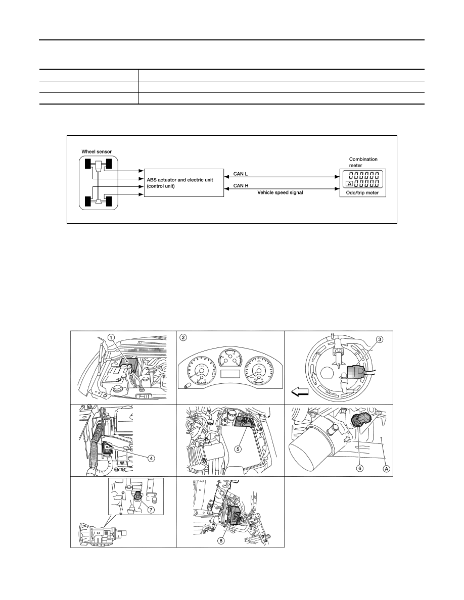
ODO/TRIP METER : System Diagram

INFOID:0000000006164891

ODO/TRIP METER : System Description

INFOID:0000000006164892

The vehicle speed signal and the memory signals from the meter memory circuit are processed by the combi-

nation meter and the mileage is displayed.

HOW TO CHANGE THE DISPLAY FOR ODO/TRIP METER

Refer to Owner's Manual for odo/trip meter operating instructions.

ODO/TRIP METER : Component Parts Location

INFOID:0000000006164893

Unit

Description

Combination meter

Indicates the battery voltage according to the voltage signal received from the fuse block (J/B).

Fuse block (J/B)

Transmits the battery voltage signal to the combination meter.

AWNIA0005GB

AWNIA0190ZZ

MWI

METER SYSTEM

MWI-19

< SYSTEM DESCRIPTION >

C

D

E

F

G

H

I

J

K

L

M

B

A

O

P

ODO/TRIP METER : Component Description

INFOID:0000000006164894

SHIFT POSITION INDICATOR
SHIFT POSITION INDICATOR : System Diagram

INFOID:0000000006164895

SHIFT POSITION INDICATOR : System Description

INFOID:0000000006164896

The TCM receives A/T indicator signals from the transmission range switch. The TCM then sends A/T position

indicator signals to the combination meter via CAN communication lines. The combination meter indicates the

received shift position.

1.

IPDM E/R E122, E124

2.

Combination meter M24, M25

3.

Fuel level sensor unit and fuel pump 
(view with fuel tank removed)
C7 (with Flexible Fuel)
C5 (without Flexible Fuel)
⇐: Front

4.

ECM E16 (view with battery removed) 5.

ABS actuator and electric unit (control 
unit)
E125

6.

Oil pressure switch F4
A: Oil pan (upper)

7.

A/T assembly
F9 (with floor shift)
F17 (with column shift)

8.

BCM M18, M19 (view with instrument 
lower panel LH removed)

Unit

Description

Combination meter

Converts the vehicle speed signal received from the ABS actuator and electric unit (control unit) via 
CAN communication to mileage, and it displays the accumulated mileage to the odo/trip meter. 

ABS actuator and electric unit
(control unit)

Transmits the vehicle speed signal to the combination meter via CAN communication. 

AWNIA1906GB

MWI-20

< SYSTEM DESCRIPTION >

METER SYSTEM

SHIFT POSITION INDICATOR : Component Parts Location

INFOID:0000000006164897

SHIFT POSITION INDICATOR : Component Description

INFOID:0000000006164898

WARNING LAMPS/INDICATOR LAMPS

1.

IPDM E/R E122, E124

2.

Combination meter M24, M25

3.

Fuel level sensor unit and fuel pump 
(view with fuel tank removed)
C7 (with Flexible Fuel)
C5 (without Flexible Fuel)
⇐: Front

4.

ECM E16 (view with battery removed) 5.

ABS actuator and electric unit (control 
unit)
E125

6.

Oil pressure switch F4
A: Oil pan (upper)

7.

A/T assembly
F9 (with floor shift)
F17 (with column shift)

8.

BCM M18, M19 (view with instrument 
lower panel LH removed)

AWNIA0190ZZ

Unit

Description

Combination meter

Displays the shift position on the information display using shift position signal received from TCM.

TCM

Transmits the shift position signal to the combination meter via CAN communication. 

MWI

METER SYSTEM

MWI-21

< SYSTEM DESCRIPTION >

C

D

E

F

G

H

I

J

K

L

M

B

A

O

P

WARNING LAMPS/INDICATOR LAMPS : System Diagram

INFOID:0000000006164899

WARNING LAMPS/INDICATOR LAMPS : System Description

INFOID:0000000006164900

OIL PRESSURE WARNING LAMP

• IPDM E/R reads the ON/OFF signals from the oil pressure switch and transmits the oil pressure switch sig-

nal to the combination meter via BCM with the CAN communication line. 

• The combination meter turns the oil pressure warning lamp ON/OFF according to the oil pressure switch sig-

nal received via CAN communication. 

WARNING LAMPS/INDICATOR LAMPS : Component Parts Location

INFOID:0000000006164901

JSNIA0449GB

1.

IPDM E/R E122, E124

2.

Combination meter M24, M25

3.

Fuel level sensor unit and fuel pump 
(view with fuel tank removed)
C7 (with Flexible Fuel)
C5 (without Flexible Fuel)
⇐: Front

4.

ECM E16 (view with battery removed) 5.

ABS actuator and electric unit (control 
unit)
E125

6.

Oil pressure switch F4
A: Oil pan (upper)

7.

A/T assembly
F9 (with floor shift)
F17 (with column shift)

8.

BCM M18, M19 (view with instrument 
lower panel LH removed)

AWNIA0190ZZ


Content   ..  724  725  726  727   ..