Nissan Titan A60. Manual - part 649


  Index      Nissan     Nissan Titan A60 (2011 year) - Service and Repair Manual


Search            


Content   ..  647  648  649  650   ..


Nissan Titan A60. Manual - part 649


BATTERY SAVER OUTPUT/POWER SUPPLY CIRCUIT

INL-17

< DTC/CIRCUIT DIAGNOSIS >

C

D

E

F

G

H

I

J

K

M

A

B

INL

N

O

P

BATTERY SAVER OUTPUT/POWER SUPPLY CIRCUIT

Description

INFOID:0000000006164461

Provides the battery saver output/power supply. Cuts the power supply when the interior room lamp battery

saver is activating.

Component Function Check

INFOID:0000000006164462

1.

CHECK BATTERY SAVER OUTPUT/POWER SUPPLY FUNCTION

CONSULT-III

1. Turn ignition switch ON.

2. Turn interior room lamp ON.

-

Room lamp (if equipped)

-

Front room/map lamp assembly (if equipped)

3. Select “BATTERY SAVER” of BCM (BATTERY SAVER) active test item.

4.  While operating the test item, check that interior room lamp turns ON/OFF.

Is the inspection result normal?

YES

>> Battery saver output/power supply circuit is normal.

NO

>> Refer to 

INL-17, "Diagnosis Procedure"

.

Diagnosis Procedure

INFOID:0000000006164463

Regarding Wiring Diagram information, refer to 

INL-39, "Wiring Diagram"

.

1.

CHECK BATTERY SAVER OUTPUT/POWER SUPPLY OUTPUT

CONSULT-III

1. Turn ignition switch ON.

2. Select “BATTERY SAVER” of BCM (BATTERY SAVER) active

test item.

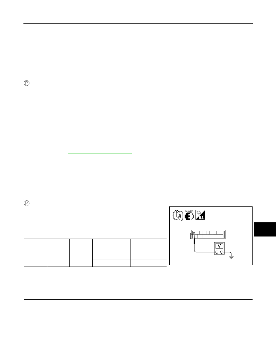
3. While operating the test item, check voltage between BCM con-

nector M20 terminal 56 and ground.

Is the inspection result normal?

YES

>> GO TO 2

NO

>> Replace BCM after making sure the battery saver output/power supply circuit is not shorted to

voltage. Refer to 

BCS-53, "Removal and Installation"

.

2.

CHECK BATTERY SAVER OUTPUT/POWER SUPPLY OPEN CIRCUIT

1. Turn ignition switch OFF.

2. Disconnect the following connectors.

-

BCM  M20

-

Front step lamp LH (if equipped)

-

Front step lamp RH (if equipped)

-

Door mirror LH (with puddle lamps)

-

Door mirror RH (with puddle lamps)

-

Foot lamp LH (if equipped)

OFF

: Interior room lamp OFF

ON

: Interior room lamp ON

(+)

(-)

Test item

Voltage

Connector

Terminal

BATTERY SAVER

M20

56

Ground

OFF

0V

ON

Battery voltage

ALLIA0408GB

INL-18

< DTC/CIRCUIT DIAGNOSIS >

BATTERY SAVER OUTPUT/POWER SUPPLY CIRCUIT

-

Foot lamp RH (if equipped)

-

Room lamp (if equipped)

-

Front room/map lamp assembly (if equipped)

-

Vanity lamp LH (if equipped)

-

Vanity lamp RH (if equipped)

-

Personal lamp 2nd row (if equipped)

3. Check continuity between BCM connector M20 terminal 56 and each interior room lamp connector.

Is the inspection result normal?

YES

>> GO TO 3

NO

>> Repair the harness or connectors.

3.

CHECK BATTERY SAVER OUTPUT/POWER SUPPLY SHORT CIRCUIT

Check continuity between BCM connector M20 terminal 56 and

ground.

Is the inspection result normal?

YES

>> Check that each interior room lamp has no internal short

circuit.

NO

>> Repair the harness or connectors.

BCM

Each interior room lamp

Continuity

Connector

Terminal

Connector

Terminal

M20

56

Front step lamp LH (if equipped)

D11

1

Yes

Front step lamp RH (if equipped)

D109

1

Door mirror LH (with puddle lamps)

D4

12

Door mirror RH (with puddle lamps)

D107

12

Foot lamp LH (if equipped)

M99

1

Foot lamp RH (if equipped)

M100

1

Room lamp (if equipped)

R10

2

Front room/map lamp assembly (if equipped)

R102

6

Vanity lamp LH (if equipped)

R3

1

Vanity lamp RH (if equipped)

R8

1

Personal lamp 2nd row (if equipped)

R203

3

Connector

Terminal

Continuity

M20

56

Ground

No

ALLIA0409GB

INTERIOR ROOM LAMP CONTROL CIRCUIT

INL-19

< DTC/CIRCUIT DIAGNOSIS >

C

D

E

F

G

H

I

J

K

M

A

B

INL

N

O

P

INTERIOR ROOM LAMP CONTROL CIRCUIT

Description

INFOID:0000000006164464

Controls the following interior room lamps (ground side) by pulse width modulated signal

• Puddle lamps (with puddle lamps)

• Room lamp (if equipped)

• Front room/map lamp assembly (if equipped)

• Personal lamp 2nd row (if equipped)

NOTE:

PWM signal control period is approximately 250 Hz (in the gradual brightening/dimming).

Component Function Check

INFOID:0000000006164465

CAUTION:

 Before performing the diagnosis, check that the following is normal.

• Battery saver output/power supply

• Room lamp bulb (if equipped)

• Puddle lamp bulbs (if equipped)

• Front room/map lamp assembly bulbs (if equipped)

• Personal lamp 2nd row bulbs (if equipped)

1.

CHECK INTERIOR ROOM LAMP CONTROL FUNCTION

CONSULT-III

1. Switch the room lamp (if equipped), or front room/map lamp assembly (if equipped) switch to DOOR.

2. Turn ignition switch ON.

3. Select “INT LAMP” of BCM (INT LAMP) active test item.

4. While operating the test item, check that each interior room lamp turns ON/OFF (gradual brightening/dim-

ming).

Is the inspection result normal?

YES

>> Interior room lamp control circuit is normal.

NO

>> Refer to 

INL-19, "Diagnosis Procedure"

.

Diagnosis Procedure

INFOID:0000000006164466

Regarding Wiring Diagram information, refer to 

INL-39, "Wiring Diagram"

.

1.

CHECK INTERIOR ROOM LAMP CONTROL OUTPUT

CONSULT-III

1. Switch the room lamp (if equipped), or front room/map lamp

assembly (if equipped) switch to DOOR.

2. Turn ignition switch ON.

3. Select “INT LAMP” of BCM (INT LAMP) active test item.

4. While operating the test item, check voltage between BCM con-

nector M20 terminal 63 and ground.

Is the inspection result normal?

YES

>> Interior room lamp control circuit is operating normally.

ON

: Interior room lamp gradual brightening

OFF

: Interior room lamp gradual dimming

(+)

(-)

INT LAMP

Voltage

Connector

Terminal

M20

63

Ground

ON

0V

OFF

Battery voltage

ALLIA0410GB

INL-20

< DTC/CIRCUIT DIAGNOSIS >

INTERIOR ROOM LAMP CONTROL CIRCUIT

Fixed ON>>GO TO 3

Fixed OFF>> GO TO 2.

2.

CHECK INTERIOR ROOM LAMP CONTROL OPEN CIRCUIT

1. Turn ignition switch OFF.

2. Disconnect BCM connector M20, door mirror connectors (with

puddle lamps), room lamp connector (if equipped) or front room/

map lamp assembly connector (if equipped).

3. Check continuity between BCM connector M20 (A) terminal 63

and door mirror connectors (B) terminal 13 (with puddle lamps),

room lamp connector (C) terminal 1 (if equipped) or front room/

map lamp assembly connector (D) terminal 1 (if equipped).

4. If equipped with personal lamp 2nd row, reconnect front room/

map lamp assembly connector.

5. Disconnect personal lamp 2nd row connector.

6. Check continuity between BCM connector M20 (A) terminal 63

and personal lamp 2nd row connector R203 (B) terminal 1.

Is the inspection result normal?

YES

>> Check interior room lamps for an open. If OK, replace BCM. Refer to 

BCS-53, "Removal and

Installation"

If NG, replace interior room lamp. Refer to 

INL-72, "Removal and Installation"

.

NO

>> Repair the harness or connectors.

3.

CHECK INTERIOR ROOM LAMP CONTROL SHORT CIRCUIT

Connector

Terminal

Component

Connector

Terminal

Continuity

M20 (A)

63

Door mirror LH (with 
puddle lamps)

D4 (B)

13

Yes

Door mirror RH (with 
puddle lamps)

D107 (B)

13

Room lamp (if 
equipped)

R10 (C)

1

Front room/map 
lamp assembly (if 
equipped)

R102 (D)

1

AWLIA1608ZZ

BCM

Personal lamp 2nd row

Continuity

Connector

Terminal

Connector

Terminal

M20 (A)

63

R203 (B)

1

Yes

ALLIA0412GB


Content   ..  647  648  649  650   ..