Nissan Titan A60. Manual - part 579


  Index      Nissan     Nissan Titan A60 (2011 year) - Service and Repair Manual


Search            


Content   ..  577  578  579  580   ..


Nissan Titan A60. Manual - part 579


AMBIENT SENSOR

HA-45

< REMOVAL AND INSTALLATION >

C

D

E

F

G

H

J

K

L

M

A

B

HA

N

O

P

AMBIENT SENSOR

Removal and Installation

INFOID:0000000006163120

REMOVAL

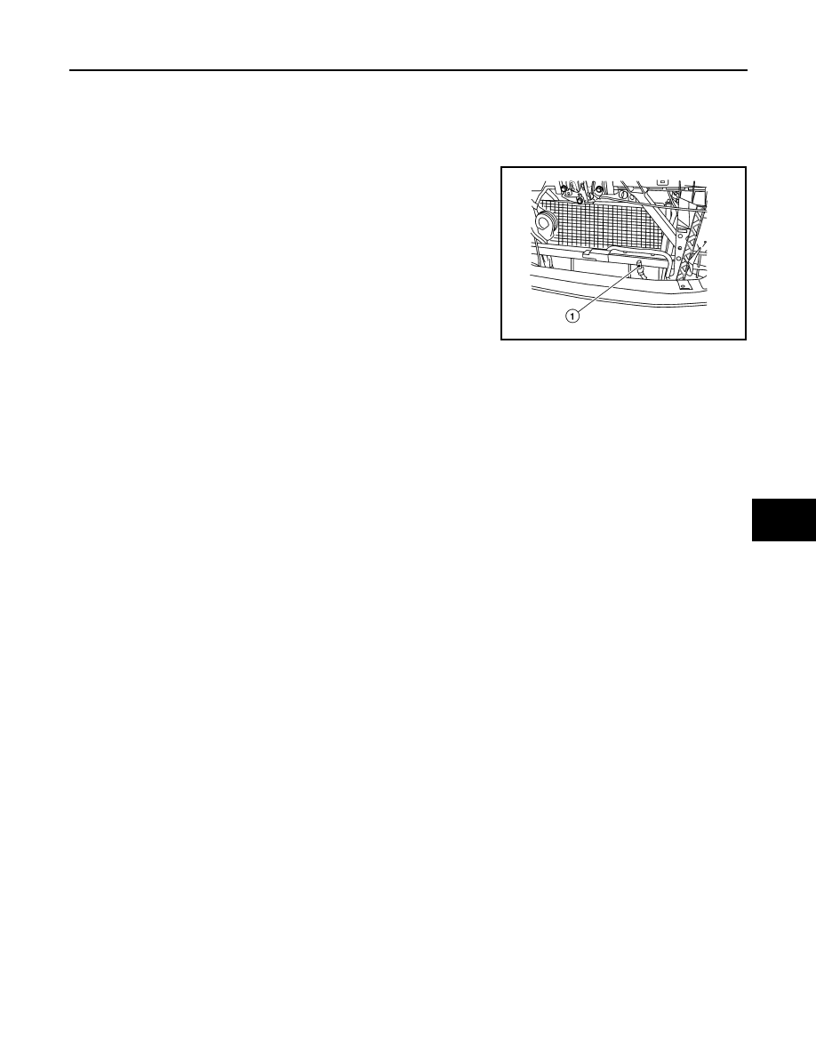
1. Disconnect the ambient sensor electrical connector.

NOTE:

The ambient sensor (1) is located behind the front bumper, in

front of the condenser (front grille removed for clarity).

2. Release the ambient sensor clip and then remove the ambient

sensor (1).

INSTALLATION

Installation is in the reverse order of removal.

AWIIA1074ZZ

HA-46

< SERVICE DATA AND SPECIFICATIONS (SDS) 

SERVICE DATA AND SPECIFICATIONS (SDS)

SERVICE DATA AND SPECIFICATIONS (SDS)

SERVICE DATA AND SPECIFICATIONS (SDS)

Service Data and Specification (SDS)

INFOID:0000000006163121

COMPRESSOR

OIL

REFRIGERANT

Make

ZEXEL VALEO CLIMATE CONTROL

Model

DKS-17D

Type

Swash plate

Displacement

175.5 cm

3

 (10.7 in

3

) / revolution

Cylinder bore 

× stroke

30.5 x 24.0 mm (1.20 x 0.94 in)

Direction of rotation

Clockwise (viewed from drive end)

Drive belt

Poly V

Name

NISSAN A/C System Oil Type S (DH-PS)

Capacity

200 m  (6.8 US fl oz, 7.0 Imp fl oz)

Type

HFC 134a (R-134a)

Capacity

0.70 

± 0.05 kg (1.54 ± 0.11 lb)

HAC-1

VENTILATION, HEATER & AIR CONDITIONER

C

D

E

F

G

H

J

K

L

M

SECTION 

HAC

A

B

HAC

N

O

P

CONTENTS

HEATER & AIR CONDITIONING CONTROL SYSTEM

AUTOMATIC AIR CONDITIONER

BASIC INSPECTION  ....................................

5

DIAGNOSIS AND REPAIR WORKFLOW  ..........

5

How to Perform Trouble Diagnosis For Quick And 
Accurate Repair  ......................................................
..

5

INSPECTION AND ADJUSTMENT .....................

6

Operational Check  ....................................................

6

SYSTEM DESCRIPTION  ..............................

8

FUNCTION INFORMATION  ................................

8

Component Part Location  .........................................

8

Symptom Table  .......................................................

10

REFRIGERATION SYSTEM  ..............................

11

Refrigerant Cycle  ....................................................

11

Refrigerant System Protection ................................

11

AUTOMATIC AIR CONDITIONER SYSTEM  .....

13

Control System Diagram  .........................................

13

Control System Description .....................................

13

Discharge Air Flow  ..................................................

15

Switches And Their Control Function ......................

16

DIAGNOSIS SYSTEM (HVAC)  ..........................

17

CONSULT-III Function (HVAC) ...............................

17

DIAGNOSIS SYSTEM (BCM)  ............................

19

CONSULT-III Function (BCM - COMMON ITEM) ....

19

CONSULT-III Function (BCM - AIR CONDITION-
ER) ..........................................................................

19

SELF-DIAGNOSIS FUNCTION ..........................

21

Front Air Control Self-Diagnosis ..............................

21

Front Air Control Self-Diagnosis Code Chart  ..........

21

DTC/CIRCUIT DIAGNOSIS  .........................

22

MODE DOOR MOTOR  .......................................

22

System Description  .................................................

22

Mode Door Motor Component Function Check  .......

23

Mode Door Motor Diagnosis Procedure  ..................

23

AIR MIX DOOR MOTOR  ...................................

27

System Description ..................................................

27

Air Mix Door Motor (Driver) Component Function 
Check ......................................................................

28

Air Mix Door Motor (Driver) Diagnosis Procedure ....

28

Air Mix Door Motor (Passenger) Component 
Function Check ........................................................

31

Air Mix Door Motor (Passenger) Diagnosis Proce-
dure .........................................................................

32

INTAKE DOOR MOTOR  ...................................

35

System Description ..................................................

35

Intake Door Motor Component Function Check  ......

36

Intake Door Motor Diagnosis Procedure  .................

36

DEFROSTER DOOR MOTOR CIRCUIT ...........

38

System Description ..................................................

38

Defroster Door Motor Component Function Check 

....

38

Defroster Door Motor Diagnosis Procedure  ............

39

BLOWER MOTOR CONTROL SYSTEM ..........

43

System Description ..................................................

43

Front Blower Motor Component Function Check ....

44

Front Blower Motor Diagnosis Procedure ................

44

Front Blower Motor Component Inspection  .............

48

MAGNET CLUTCH  ...........................................

49

System Description ..................................................

49

Magnet Clutch Component Function Check ............

49

Magnet Clutch Diagnosis Procedure  .......................

49

WATER VALVE CIRCUIT  .................................

54

Description ...............................................................

54

Water Valve Diagnosis Procedure ...........................

54

AMBIENT SENSOR  ..........................................

56

Component Description  ...........................................

56

Ambient Sensor Diagnosis Procedure .....................

56

HAC-2

Ambient Sensor Component Inspection  .................

57

IN-VEHICLE SENSOR .......................................

59

Component Description  ..........................................

59

In-Vehicle Sensor Diagnosis Procedure .................

59

In-Vehicle Sensor Component Inspection  ..............

61

OPTICAL SENSOR  ...........................................

62

Component Description  ..........................................

62

Optical Sensor Diagnosis Procedure ......................

62

INTAKE SENSOR ..............................................

64

System Description .................................................

64

Intake Sensor Diagnosis Procedure  .......................

64

Intake Sensor Component Inspection  ....................

65

POWER SUPPLY AND GROUND CIRCUIT 
FOR CONTROLLER ..........................................

67

Component Description  ..........................................

67

Front Air Control Component Function Check ........

67

Front Air Control Power and Ground Diagnosis 
Procedure ..............................................................
.

67

ECU DIAGNOSIS INFORMATION ..............

69

AIR CONDITIONER CONTROL  ........................

69

Front Air Control Terminals Reference Values  .......

69

WIRING DIAGRAM  .....................................

71

AIR CONDITIONER CONTROL  ........................

71

Wiring Diagram - Automatic Air Conditioner  ...........

71

SYMPTOM DIAGNOSIS  .............................

82

AIR CONDITIONER CONTROL  ........................

82

Symptom Matrix Chart ..........................................

82

INSUFFICIENT COOLING .................................

83

Component Function Check  ...................................

83

Diagnostic Work Flow .............................................

84

Performance Chart  .................................................

86

Trouble Diagnoses for Abnormal Pressure  ............

87

INSUFFICIENT HEATING  .................................

91

Component Function Check  ...................................

91

NOISE ................................................................

93

Component Function Check  ...................................

93

MEMORY FUNCTION DOES NOT OPERATE ...

94

Memory Function Check .........................................

94

PRECAUTION .............................................

95

PRECAUTIONS  .................................................

95

Precaution for Supplemental Restraint System 
(SRS) "AIR BAG" and "SEAT BELT PRE-TEN-
SIONER" ................................................................
.

95

Working with HFC-134a (R-134a)  ..........................

95

Precaution for Service Equipment  ..........................

96

MANUAL A/C (TYPE 1)

BASIC INSPECTION ..................................

97

MANUAL A/C IDENTIFICATION TABLE ..........

97

Application Table  ....................................................

97

DIAGNOSIS AND REPAIR WORKFLOW .........

98

How to Perform Trouble Diagnosis For Quick And 
Accurate Repair  ......................................................

98

INSPECTION AND ADJUSTMENT ...................

99

Operational Check  ..................................................

99

SYSTEM DESCRIPTION  ..........................

101

MANUAL A/C IDENTIFICATION TABLE .........

101

Application Table  ..................................................

101

FUNCTION INFORMATION  .............................

102

Component Part Location  .....................................

102

Symptom Table .....................................................

104

REFRIGERATION SYSTEM .............................

105

Refrigerant Cycle  ..................................................

105

Refrigerant System Protection ..............................

105

MANUAL AIR CONDITIONER SYSTEM  .........

107

Control System Diagram .......................................

107

Control System Description ..................................

107

Discharge Air Flow ................................................

109

Switches And Their Control Function ....................

109

DIAGNOSIS SYSTEM (HVAC) .........................

111

CONSULT-III Function (HVAC)  ............................

111

DIAGNOSIS SYSTEM (BCM) ...........................

112

CONSULT-III Function (BCM - COMMON ITEM) .

112

CONSULT-III Function (BCM - AIR CONDITION-
ER) ........................................................................

112

SELF-DIAGNOSIS FUNCTION  ........................

114

Front Air Control Self-Diagnosis  ...........................

114

Front Air Control Self-Diagnosis Code Chart  ........

114

DTC/CIRCUIT DIAGNOSIS .......................

115

MANUAL A/C IDENTIFICATION TABLE .........

115

Application Table  ..................................................

115

MODE DOOR MOTOR  .....................................

116

System Description  ...............................................

116

Mode Door Motor Component Function Check  ....

116

Mode Door Motor Diagnosis Procedure ................

116

AIR MIX DOOR MOTOR  ..................................

120

System Description  ...............................................

120

Air Mix Door Motor Component Function Check  ..

120

Air Mix Door Motor Diagnosis Procedure ..............

121

INTAKE DOOR MOTOR ...................................

125

System Description  ...............................................

125

Intake Door Motor Component Function Check ....

125

Intake Door Motor Diagnosis Procedure ...............

126


Content   ..  577  578  579  580   ..