Nissan Titan A60. Manual - part 478


  Index      Nissan     Nissan Titan A60 (2011 year) - Service and Repair Manual


Search            


Content   ..  476  477  478  479   ..


Nissan Titan A60. Manual - part 478


ENGINE UNIT

EM-97

< UNIT DISASSEMBLY AND ASSEMBLY >

C

D

E

F

G

H

I

J

K

L

M

A

EM

N

P

O

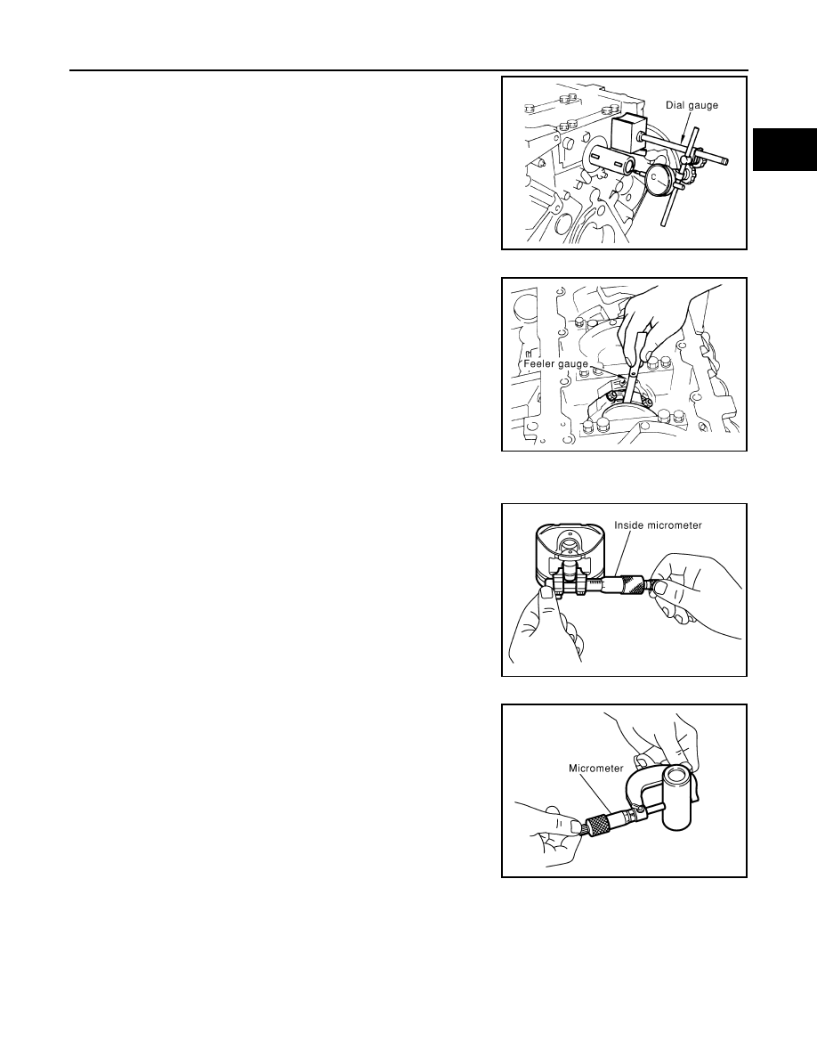
• Move the crankshaft fully forward and backward and measure the

clearance between the thrust bearings and crankshaft arm using

suitable tool.

• If measured value exceeds the repair limit, replace the thrust bear-

ings, and measure again. If it still exceeds the repair limit, replace

crankshaft also.

CONNECTING ROD SIDE CLEARANCE

• Measure side clearance between the connecting rod and crank-

shaft arm using suitable tool.

• If measured value exceeds the repair limit, replace the connecting

rod bearings, and measure again. If it still exceeds the repair limit,

replace the crankshaft also.

PISTON AND PISTON PIN CLEARANCE

Piston Pin Hole Diameter

• Measure diameter of piston pin hole using suitable tool.

Piston Pin Diameter 

• Measure diameter of piston pin using suitable tool.

Piston and Piston Pin Clearance

Standard

: 0.10 - 0.26 mm (0.0039 - 0.0102 in)

Limit

: 0.30 mm (0.0118 in)

PBIC0114E

Standard

: 0.20 - 0.40 mm (0.0079 - 0.0157 in)

Limit

: 0.40 mm (0.0157 in)

PBIC0115E

Standard

: 21.993 - 21.999 mm (0.8659 - 0.8661 in)

PBIC0116E

Standard

: 21.989 - 21.995 mm (0.8657 - 0.8659 in)

PBIC0117E

EM-98

< UNIT DISASSEMBLY AND ASSEMBLY >

ENGINE UNIT

(Piston pin clearance) = (Piston pin hole diameter) – (Piston pin

diameter)

• If clearance exceeds specification, replace either or both the pis-

ton/piston pin assembly and the connecting rod assembly with ref-

erence to the specification of each part.

• Use the piston selection table to replace piston/piston pin assem-

bly. Refer to 

EM-107, "How to Select Piston and Bearing"

.

• Use the connecting rod bearing selection table to replace connect-

ing rod. Refer to 

EM-107, "How to Select Piston and Bearing"

.

NOTE:

The connecting rod small end grade and piston pin hole (piston

pin) grade are provided only for the parts installed at the plant. For

service parts, no grades can be selected (only 0 grade is avail-

able). 

• Follow "Connecting Rod Bushing Oil Clearance (Small End)" for

the values for each grade at the plant.

PISTON RING SIDE CLEARANCE

• Measure side clearance of the piston ring and piston ring groove

using suitable tool.

• If out of specification, replace piston and/or piston ring assembly.

PISTON RING END GAP

• Check if the diameter of the cylinder bore is within specification.

Refer to 

EM-114, "Standard and Limit"

.

• Insert the piston ring into the middle of the cylinder using the pis-

ton, and measure the gap.

• If out of specification, replace piston ring. 

Standard

: 0.002 - 0.006 mm (0.0001 - 0.0002 in)

KBIA2496E

KBIA2536E

Standard:

Top ring

: 0.035 - 0.085 mm (0.0014 - 0.0033 in)

2nd ring

: 0.030 - 0.070 mm (0.0012 - 0.0028 in)

Oil ring

: 0.015 - 0.185 mm (0.0006 - 0.0073 in)

Limit:

Top ring

: 0.11 mm (0.0043 in)

2nd ring

: 0.10 mm (0.0039 in)

SEM024AA

Standard

Top ring

: 0.23 - 0.33 mm (0.0091 - 0.0130 in)

2nd ring

: 0.25 - 0.40 mm (0.0098 - 0.0157 in)

Oil ring

: 0.20 - 0.60 mm (0.0079 - 0.0236 in)

Limit:

Top ring

: 0.56 mm (0.0220 in)

2nd ring

: 0.52 mm (0.0205 in)

Oil ring

: 0.96 mm (0.0378 in)

PBIC0118E

ENGINE UNIT

EM-99

< UNIT DISASSEMBLY AND ASSEMBLY >

C

D

E

F

G

H

I

J

K

L

M

A

EM

N

P

O

CONNECTING ROD BEND AND TORSION

• Check connecting rod alignment using suitable tool.

• If measurement exceeds the limit, replace connecting rod assem-

bly.

CONNECTING ROD BEARING (BIG END)

• Install the connecting rod cap without the connecting rod bearing

installed. After tightening the connecting rod bolt to the specified

torque, measure the connecting rod large end inside diameter.

Refer to 

EM-89, "Disassembly and Assembly"

.

• If measurement exceeds the standard, replace connecting rod.

CONNECTING ROD BUSHING OIL CLEARANCE (SMALL END)

 Connecting Rod Inside Diameter (Small End)

• Measure inside diameter of bushing using suitable tool.

Piston Pin Diameter

Limit:

Bend

: 0.15 mm (0.0059 in) per 100 mm (3.94 in) length

Torsion

: 0.30 mm (0.0118 in) per 100 mm (3.94 in) length

SEM003F

SEM038F

Standard

: 57.000 - 57.013 mm (2.2441 - 2.2446 in)

PBIC1641E

Standard

: 22.000 - 22.006 mm (0.8661 - 0.8664 in)

PBIC0120E

EM-100

< UNIT DISASSEMBLY AND ASSEMBLY >

ENGINE UNIT

• Measure diameter of piston pin using suitable tool.

Connecting Rod Bushing Oil Clearance (Small End)

(Connecting rod small end oil clearance) = (Inside diameter of con-

necting rod small end) – (Piston pin diameter)

• If measured value exceeds the standard, replace the connecting

rod assembly and/or piston and piston pin assembly.

• If replacing the piston and piston pin assembly, use the Table for

Selective Fitting for Piston to select the piston corresponding to the

applicable bore grade of the cylinder block to be used. Refer to

EM-107, "How to Select Piston and Bearing"

.

Factory installed parts grading:

• Only grade 0 is available.

Unit: mm (in)

CYLINDER BLOCK DISTORTION

• Remove any oil, scale, gasket, sealant and carbon deposits from the cylinder block surface.

CAUTION:

Do not allow any debris to enter the oil or coolant passages.

• Measure block upper face for distortion in six directions as shown.

• If measurement exceeds the limit, replace cylinder block.

MAIN BEARING HOUSING INSIDE DIAMETER

Standard

: 21.989 - 21.995 mm (0.8657 - 0.8659 in)

PBIC0117E

Standard

: 0.005 - 0.017 mm (0.0002 - 0.0007 in)

KBIA2536E

Grade

0

Connecting rod bushing inside diameter

22.000 - 22.006          

       (0.8661 - 0.8664)

Piston pin diameter

21.989 - 21.995

(0.8657 - 0.8659)

Piston pin hole diameter

21.993 - 21.999

(0.8659 - 0.8661)

KBIA2496E

Standard

: 0.03 mm (0.0012 in)

Limit

: 0.1 mm (0.004 in)

SEM123C


Content   ..  476  477  478  479   ..