Nissan Titan A60. Manual - part 458


  Index      Nissan     Nissan Titan A60 (2011 year) - Service and Repair Manual


Search            


Content   ..  456  457  458  459   ..


Nissan Titan A60. Manual - part 458


SPARK PLUG

EM-17

< PERIODIC MAINTENANCE >

C

D

E

F

G

H

I

J

K

L

M

A

EM

N

P

O

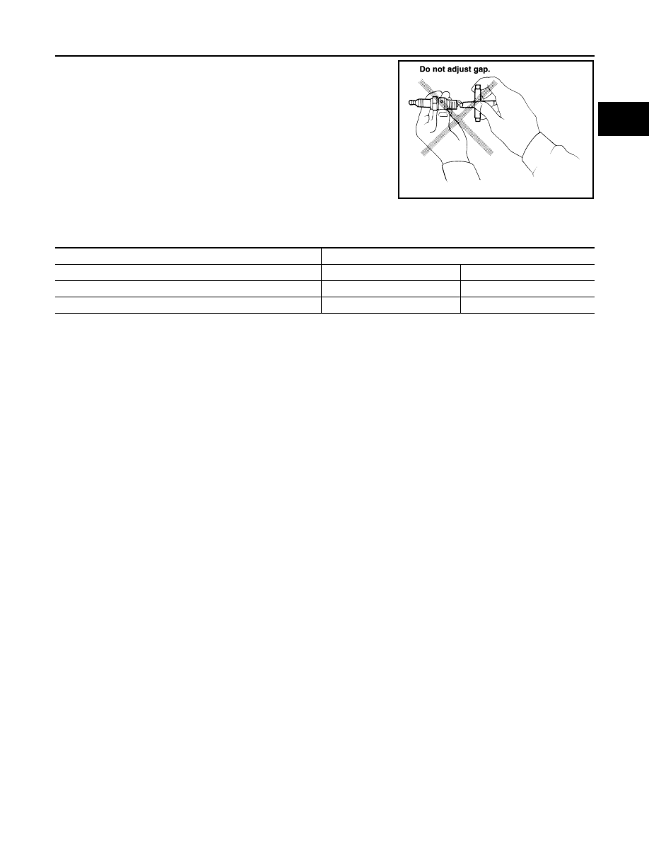
• Checking and adjusting plug gap is not required between change

intervals.

INSTALLATION

Installation is in the reverse order of removal.

Spark Plug Types

*: Always check with the Parts Department for the latest parts information.

CAUTION:

Do not drop or shock spark plug.

SMA806CA

Make

NGK

Model

Standard model

FFV model

Standard type*

DILFR5A-11

DILFR5A-11D

Gap (Nominal)

1.1 mm (0.043 in)

1.1 mm (0.043)

EM-18

< PERIODIC MAINTENANCE >

CAMSHAFT VALVE CLEARANCE

CAMSHAFT VALVE CLEARANCE

Valve Clearance

INFOID:0000000006179386

INSPECTION

NOTE:

Perform the following inspection after removal, installation or replacement of camshaft or valve-related parts,

or if there are unusual engine conditions due to changes in valve clearance over time (starting, idling, and/or

noise).
1. Warm up the engine. Then stop the engine.
2. Remove the air cleaner and resonator assembly. Refer to 

EM-25, "Removal and Installation"

.

3. Remove the RH bank and LH bank rocker covers using power tool. Refer to 

EM-39, "Removal and Instal-

lation"

.

4. Turn the crankshaft pulley in the normal direction (clockwise

when viewed from engine front) to align TDC identification notch

(without paint mark) with timing indicator.

5. At this time, make sure both the intake and exhaust cam noses

of No. 1 cylinder (top front on LH bank) face outside.

• If they do not face outside, turn crankshaft pulley once more.

KBIA2476E

KBIA0400J

CAMSHAFT VALVE CLEARANCE

EM-19

< PERIODIC MAINTENANCE >

C

D

E

F

G

H

I

J

K

L

M

A

EM

N

P

O

6. Measure valve clearances at the locations marked “

×” as shown

in the table below (locations indicated with black arrow).

: Engine front

 (black): Measurable at No.1 cylinder compression top dead

center

 (white): Measurable at No. 3 cylinder compression top

dead center

• A:  RH

• B:  LH 

• C: Exhaust

• D: Intake

NOTE:

Firing order 1-8-7-3-6-5-4-2

• No. 1 cylinder compression TDC

• Measure valve clearance using suitable tool. Refer to 

EM-114,

"Standard and Limit"

.

CAUTION:

If the inspection was carried out with a cold engine, make

sure the values with a fully warmed up engine are still

within specifications.

7. Turn the crankshaft pulley clockwise 270

° from the position of No. 1 cylinder compression TDC to obtain

No. 3 cylinder compression TDC.

Measuring position (RH bank)

No. 2 cyl 

(E)

No. 4 cyl 

(F)

No. 6 cyl 

(G)

No. 8 cyl 

(H)

No. 1 cylinder at TDC

 EXH

×

INT

×

×

Measuring position (LH bank)

No. 1 cyl 

(J)

No. 3 cyl 

(K)

No. 5 cyl 

(L)

No. 7 cyl 

(M)

No. 1 cylinder at TDC

INT

×

×

EXH

×

×

WBIA0713E

KBIA0185E

EM-20

< PERIODIC MAINTENANCE >

CAMSHAFT VALVE CLEARANCE

8. Measure valve clearances at the locations marked “

×” as shown

in the table below (locations indicated with white arrow).

: Engine front

 (black): Measurable at No.1 cylinder compression top dead

center

 (white): Measurable at No. 3 cylinder compression top

dead center

• A:  RH

• B:  LH 

• C: Exhaust

• D:  Intake

NOTE:

Firing order 1-8-7-3-6-5-4-2

• No. 3 cylinder compression TDC

• Measure valve clearance using suitable tool. Refer to 

EM-114,

"Standard and Limit"

.

CAUTION:

If the inspection was carried out with a cold engine, make

sure the values with a fully warmed up engine are still

within specifications.

Measuring position (RH bank)

No. 2 cyl 

(E)

No. 4 cyl 

(F)

No. 6 cyl 

(G)

No. 8 cyl 

(H)

No. 3 cylinder at TDC

 EXH

×

INT

×

Measuring position (LH bank)

No. 1 cyl 

(J)

No. 3 cyl 

(K)

No. 5 cyl 

(L)

No. 7 cyl 

(M)

No. 3 cylinder at TDC

INT

×

×

EXH

×

×

WBIA0713E

KBIA0185E


Content   ..  456  457  458  459   ..