Nissan Titan A60. Manual - part 436
EC-410
< DTC/CIRCUIT DIAGNOSIS >
[VK56DE]
P2118 THROTTLE CONTROL MOTOR
2.
CHECK THROTTLE CONTROL MOTOR OUTPUT SIGNAL CIRCUIT FOR OPEN OR SHORT
1. Disconnect electric throttle control actuator (1) harness connec-
tor.
-
Illustration shows the view with intake air duct removed.
2. Disconnect ECM harness connector.
3. Check harness continuity between the following terminals.
Refer to Wiring Diagram.
4. Also check harness for short to ground and short to power.
OK or NG
OK
>> GO TO 3.
NG
>> Repair or replace.
3.
CHECK THROTTLE CONTROL MOTOR
EC-410, "Component Inspection"
OK or NG
OK
>> GO TO 4.
NG
>> GO TO 5.
4.
CHECK INTERMITTENT INCIDENT
GI-36, "How to Check Terminal"
and
GI-39, "Intermittent Incident"
OK or NG
OK
>> GO TO 5.
NG
>> Repair or replace harness or connectors.
5.
REPLACE ELECTRIC THROTTLE CONTROL ACTUATOR
1. Replace the electric throttle control actuator.
2. Perform
EC-119, "Throttle Valve Closed Position Learning"
3. Perform
EC-120, "Idle Air Volume Learning"
.
>> INSPECTION END
Component Inspection
INFOID:0000000006158888
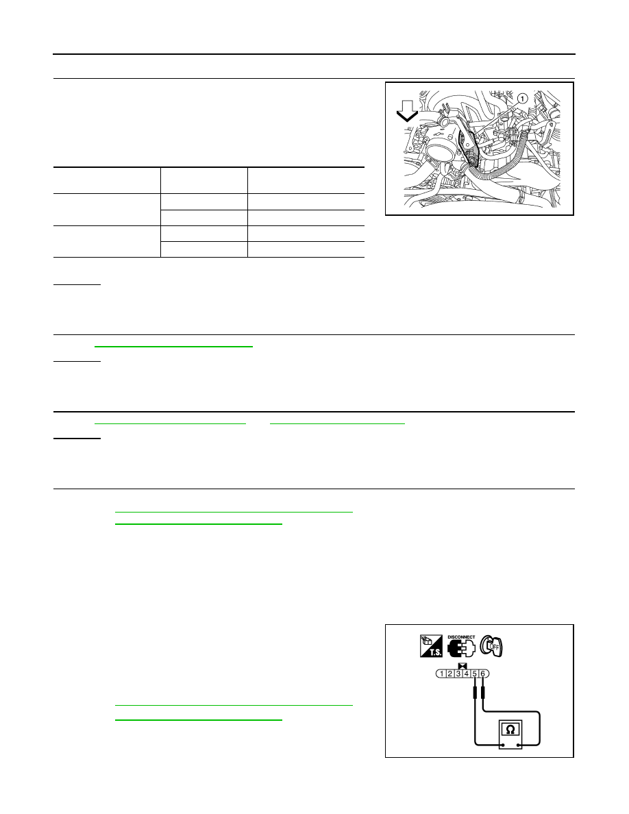
THROTTLE CONTROL MOTOR
1. Disconnect electric throttle control actuator harness connector.
2. Check resistance between terminals 5 and 6.
3. If NG, replace electric throttle control actuator and go to next
step.
4. Perform
EC-119, "Throttle Valve Closed Position Learning"
5. Perform
EC-120, "Idle Air Volume Learning"
.
Electric throttle control
actuator terminal
ECM terminal
Continuity
5
5
Should not exist
4 Should
exist
6
5
Should exist
4
Should not exist
BBIA0776E
Resistance: Approximately 1 - 15
Ω [at 25 °C (77°F)]
PBIB2066E