Nissan Titan A60. Manual - part 414


  Index      Nissan     Nissan Titan A60 (2011 year) - Service and Repair Manual


Search            


Content   ..  412  413  414  415   ..


Nissan Titan A60. Manual - part 414


EC-322

< DTC/CIRCUIT DIAGNOSIS >

[VK56DE]

P0456 EVAP CONTROL SYSTEM

NG

>> Repair or replace EVAP canister vent control valve and O-ring.

10.

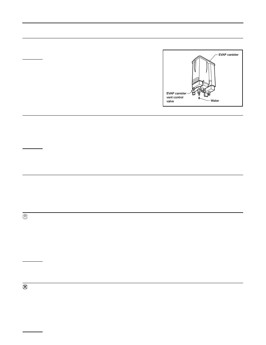
CHECK IF EVAP CANISTER SATURATED WITH WATER

1. Remove EVAP canister with EVAP canister vent control valve and EVAP control system pressure sensor

attached.

2. Does water drain from the EVAP canister?
Yes or No

Yes

>> GO TO 11.

No (With CONSULT-III)>>GO TO 13.

No (Without CONSULT-III)>>GO TO 14.

11.

CHECK EVAP CANISTER

Weigh the EVAP canister with the EVAP canister vent control valve and EVAP control system pressure sensor

attached.

OK or NG

OK (With CONSULT-III)>>GO TO 13.

OK (Without CONSULT-III)>>GO TO 14.

NG

>> GO TO 12.

12.

DETECT MALFUNCTIONING PART

Check the following.

• EVAP canister for damage

• EVAP hose between EVAP canister and drain filter for clogging or poor connection

>> Repair hose or replace EVAP canister.

13.

CHECK EVAP CANISTER PURGE VOLUME CONTROL SOLENOID VALVE OPERATION

 With CONSULT-III

1. Disconnect vacuum hose to EVAP canister purge volume control solenoid valve at EVAP service port.

2. Start engine.

3. Perform “PURG VOL CONT/V” in “ACTIVE TEST” mode.

4. Touch “Qu” on CONSULT-III screen to increase “PURG VOL CONT/V” opening to 100%.

5. Check vacuum hose for vacuum when revving engine up to 2,000 rpm.

OK or NG

OK

>> GO TO 16.

NG

>> GO TO 15.

14.

CHECK EVAP CANISTER PURGE VOLUME CONTROL SOLENOID VALVE OPERATION

 Without CONSULT-III

1. Start engine and warm it up to normal operating temperature.

2. Stop engine.

3. Disconnect vacuum hose to EVAP canister purge volume control solenoid valve at EVAP service port.

4. Start engine and let it idle for at least 80 seconds.

5. Check vacuum hose for vacuum when revving engine up to 2,000 rpm.

OK or NG

BBIA0351E

SWB models:

The weight should be less than 2.5 kg (5.5 lb).

LWB models:

The weight should be less than 3.2 kg (7.1 lb).

Vacuum should exist.

Vacuum should exist.

P0456 EVAP CONTROL SYSTEM

EC-323

< DTC/CIRCUIT DIAGNOSIS >

[VK56DE]

C

D

E

F

G

H

I

J

K

L

M

A

EC

N

P

O

OK

>> GO TO 17.

NG

>> GO TO 15.

15.

CHECK VACUUM HOSE

Check vacuum hoses for clogging or disconnection. Refer to 

EC-31, "Description"

.

OK or NG

OK

>> GO TO 16.

NG

>> Repair or reconnect the hose.

16.

CHECK EVAP CANISTER PURGE VOLUME CONTROL SOLENOID VALVE

Refer to 

EC-288, "Component Inspection"

.

OK or NG

OK

>> GO TO 17.

NG

>> Replace EVAP canister purge volume control solenoid valve.

17.

CHECK FUEL TANK TEMPERATURE SENSOR

Refer to 

EC-239, "Component Inspection"

.

OK or NG

OK

>> GO TO 18.

NG

>> Replace fuel level sensor unit.

18.

CHECK EVAP CONTROL SYSTEM PRESSURE SENSOR

Refer to 

EC-299, "Component Inspection"

.

OK or NG

OK

>> GO TO 19.

NG

>> Replace EVAP control system pressure sensor.

19.

CHECK EVAP PURGE LINE

Check EVAP purge line (pipe, rubber tube, fuel tank and EVAP canister) for cracks or improper connection.

Refer to 

EC-31, "Description"

.

OK or NG

OK

>> GO TO 20.

NG

>> Repair or reconnect the hose.

20.

CLEAN EVAP PURGE LINE

Clean EVAP purge line (pipe and rubber tube) using air blower.

>> GO TO 21.

21.

CHECK EVAP/ORVR LINE

Check EVAP/ORVR line between EVAP canister and fuel tank for clogging, kink, looseness and improper con-

nection. For location, refer to 

EC-458, "System Description"

.

OK or NG

OK

>> GO TO 22.

NG

>> Repair or replace hoses and tubes.

22.

CHECK RECIRCULATION LINE

Check recirculation line between filler neck tube and fuel tank for clogging, kink, cracks, looseness and

improper connection.
OK or NG

OK

>> GO TO 23.

NG

>> Repair or replace hose, tube or filler neck tube.

23.

CHECK REFUELING EVAP VAPOR CUT VALVE

Refer to 

EC-461, "Component Inspection"

.

OK or NG

OK

>> GO TO 24.

EC-324

< DTC/CIRCUIT DIAGNOSIS >

[VK56DE]

P0456 EVAP CONTROL SYSTEM

NG

>> Replace refueling EVAP vapor cut valve with fuel tank. 

24.

CHECK FUEL LEVEL SENSOR

Refer to 

MWI-38, "Component Inspection"

.

OK or NG

OK

>> GO TO 25.

NG

>> Replace fuel level sensor unit.

25.

CHECK INTERMITTENT INCIDENT

Refer to 

GI-36, "How to Check Terminal"

 and 

GI-39, "Intermittent Incident"

.

>> INSPECTION END

Component Inspection

INFOID:0000000006158750

FUEL TANK VACUUM RELIEF VALVE (BUILT INTO FUEL FILLER CAP)

1. Wipe clean valve housing.

2. Check valve opening pressure and vacuum.

3. If out of specification, replace fuel filler cap as an assembly.

CAUTION:

Use only a genuine fuel filler cap as a replacement. If an incor-

rect fuel filler cap is used, the MIL may come on.

DRAIN FILTER

1. Check visually for insect nests in the drain filter air inlet.
2. Check visually for cracks or flaws in the appearance.
3. Check visually for cracks or flaws in the hose.
4. Blow air into port A and check that it flows freely out of port B.
5. Block port B.
6. Blow air into port A and check that there is no leakage.
7. If NG, replace drain filter.

SEF445Y

Pressure: 15.3 - 20.0 kPa (0.156 - 0.204 kg/cm

2

, 2.22 - 

2.90 psi)

Vacuum:

6.0 to 3.3 kPa (0.061 to 0.034 kg/cm

2

0.87 to 0.48 psi)

SEF943S

PBIB3641E

P0460 FUEL LEVEL SENSOR

EC-325

< DTC/CIRCUIT DIAGNOSIS >

[VK56DE]

C

D

E

F

G

H

I

J

K

L

M

A

EC

N

P

O

P0460 FUEL LEVEL SENSOR

Component Description

INFOID:0000000006158751

The fuel level sensor is mounted in the fuel level sensor unit. The

sensor detects a fuel level in the fuel tank and transmits a signal to

the combination meter. The combination meter sends the fuel level

sensor signal to the ECM through CAN communication line.

It consists of two parts, one is mechanical float and the other is vari-

able resistor. Fuel level sensor output voltage changes depending on

the movement of the fuel mechanical float.

On Board Diagnosis Logic

INFOID:0000000006158752

NOTE:

• If DTC P0460 is displayed with DTC U0101 or U1001, first perform the trouble diagnosis for DTC

U0101, U1001. Refer to 

EC-140

.

• If DTC P0460 is displayed with DTC P0607, first perform the trouble diagnosis for DTC P0607. Refer

to 

EC-344

.

When the vehicle is parked, naturally the fuel level in the fuel tank is stable. It means that output signal of the

fuel level sensor does not change. If ECM senses sloshing signal from the sensor, fuel level sensor malfunc-

tion is detected.

DTC Confirmation Procedure

INFOID:0000000006158753

1. If DTC Confirmation Procedure has been previously conducted, always perform the following before con-

ducting the next step.

a. Turn ignition switch OFF and wait at least 10 seconds.
b. Turn ignition switch ON.
c. Turn ignition switch OFF and wait at least 10 seconds.
2. Start engine and wait maximum of 2 consecutive minutes.
3. Check 1st trip DTC.
4. If 1st trip DTC is detected, go to 

EC-325, "Diagnosis Procedure"

.

Diagnosis Procedure

INFOID:0000000006158754

1.

CHECK COMBINATION METER FUNCTION

Refer to 

MWI-28, "CONSULT-III Function (METER/M&A)"

.

OK or NG

OK

>> GO TO 2.

NG

>> Go to 

MWI-37, "Diagnosis Procedure"

.

2.

CHECK INTERMITTENT INCIDENT

Refer to 

GI-36, "How to Check Terminal"

 and 

GI-39, "Intermittent Incident"

.

BBIA0402E

DTC No.

Trouble diagnosis name

DTC detecting condition

Possible cause

P0460
0460

Fuel level sensor circuit 
noise

Even though the vehicle is parked, a signal be-
ing varied is sent from the fuel level sensor to 
ECM.

• Harness or connectors

(The CAN communication line is open or 
shorted)

• Harness or connectors

(The sensor circuit is open or shorted)

• Combination meter
• Fuel level sensor


Content   ..  412  413  414  415   ..