Nissan Titan A60. Manual - part 329


  Index      Nissan     Nissan Titan A60 (2011 year) - Service and Repair Manual


Search            


Content   ..  327  328  329  330   ..


Nissan Titan A60. Manual - part 329


DIFFERENTIAL LOCK POSITION SWITCH

DLN-255

< REMOVAL AND INSTALLATION >

[REAR FINAL DRIVE: M226 (ELD) ]

C

E

F

G

H

I

J

K

L

M

A

B

DLN

N

O

P

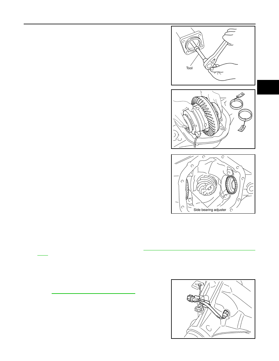
9. Loosen the side bearing adjusters using Tool.

10. Remove the differential case assembly. Keep side bearing outer

races together with inner races, do not mix them up. Also, keep

side bearing adjusters together with bearing.

11. Remove side bearing adjusters from gear carrier.

12. Remove bracket for the differential lock position switch connector and bolts.
13. Remove differential lock position switch.

INSTALLATION

1. Apply sealant to threads of differential lock position switch. 

• Use Genuine Silicone RTV or equivalent. Refer to 

GI-15, "Recommended Chemical Products and Seal-

ants"

.

CAUTION:

Remove old sealant adhering to gear carrier and differential lock position switch. Also remove any

moisture, oil, or foreign material adhering to application and gear carrier and differential lock posi-

tion switch.

2. Install differential lock position switch on gear carrier and tighten

differential lock position switch bolts with the specified torque.

Refer to 

DLN-263, "Disassembly and Assembly"

.

Tool number

 (C - 4164)

PDIA0337E

SDIA2588E

PDIA0381E

SDIA2633E

DLN-256

< REMOVAL AND INSTALLATION >

[REAR FINAL DRIVE: M226 (ELD) ]

DIFFERENTIAL LOCK POSITION SWITCH

3. Install side bearing adjusters into gear carrier.

4. Apply gear oil to side bearings. Install differential case assembly

with side bearing outer races into gear carrier.

5. Apply multi-purpose grease to differential lock position connec-

tor.

CAUTION:

Do not reuse sensor connector.

6. Connect differential lock solenoid harness (B) and differential

lock position switch connector (A). Then install it to gear carrier,

tighten to the specified torque. Refer to 

DLN-263, "Disassembly

and Assembly"

.

: Front

7. Align paint matching mark on side bearing caps with that on

gear carrier and install side bearing caps on gear carrier without

tightening to specification.

CAUTION:

Do not tighten at this point. This allows further tightening of

side bearing adjusters.

8. Tighten each side bearing adjusters using adjuster tool.

9. Adjusting backlash of drive gear and drive pinion. Refer to 

DLN-

263, "Disassembly and Assembly"

.

10. Check total preload torque. Refer to 

DLN-263, "Disassembly

and Assembly"

.

11. Check tooth contact. Refer to 

DLN-263, "Disassembly and

Assembly"

.

PDIA0381E

SDIA2588E

WDIA0331E

SDIA2632E

Tool number 

 (C - 4164)

PDIA0337E

DIFFERENTIAL LOCK POSITION SWITCH

DLN-257

< REMOVAL AND INSTALLATION >

[REAR FINAL DRIVE: M226 (ELD) ]

C

E

F

G

H

I

J

K

L

M

A

B

DLN

N

O

P

12. Apply a bead of sealant to the mating surface of the carrier

cover as shown.

• Use Genuine Silicone RTV or equivalent. Refer to 

GI-15,

"Recommended Chemical Products and Sealants"

.

CAUTION:

Remove any old sealant adhering to the mating surfaces.

Also remove any moisture, oil, or foreign material adhering

to the application and mating surfaces.

13. Install the carrier cover to the gear carrier. Tighten the bolts to

the specified torque. Refer to 

DLN-263, "Disassembly and

Assembly"

.

14. Installation of the remaining components is in the reverse order

of removal.

CAUTION:

Fill the front final drive assembly with recommended differential gear oil. Refer to 

DLN-252,

"Changing Differential Gear Oil"

.

PDIA1061E

DLN-258

< REMOVAL AND INSTALLATION >

[REAR FINAL DRIVE: M226 (ELD) ]

FRONT OIL SEAL

FRONT OIL SEAL

Removal and Installation

INFOID:0000000006179628

REMOVAL

1. Remove rear propeller shaft. Refer to 

DLN-141, "Removal and Installation"

 (2S1410), 

DLN-150, "Removal

and Installation"

 (3S1410).

2. Remove brake calipers and rotors. Refer to 

BR-36, "Removal and Installation of Brake Caliper and Disc

Rotor"

.

3. Measure the total preload torque. Refer to 

DLN-263, "Disassembly and Assembly"

.

NOTE:

Record the total preload torque measurement.

4. Remove the drive pinion nut using suitable tool.
5. Put matching marks on the companion flange and drive pinion

using paint.

CAUTION:

Use paint to make the matching marks. Do not damage the

companion flange or drive pinion.

6. Remove the companion flange using suitable tool.

7. Remove oil seal/dust shield and discard.
8. Remove the front oil seal using Tool.

INSTALLATION

LDIA0122E

LDIA0123E

Tool number

: ST33290001 (J-34286)

LDIA0124E


Content   ..  327  328  329  330   ..