Nissan Titan A60. Manual - part 311


  Index      Nissan     Nissan Titan A60 (2011 year) - Service and Repair Manual


Search            


Content   ..  309  310  311  312   ..


Nissan Titan A60. Manual - part 311


FRONT FINAL DRIVE

DLN-183

< UNIT DISASSEMBLY AND ASSEMBLY >

[FRONT FINAL DRIVE: M205]

C

E

F

G

H

I

J

K

L

M

A

B

DLN

N

O

P

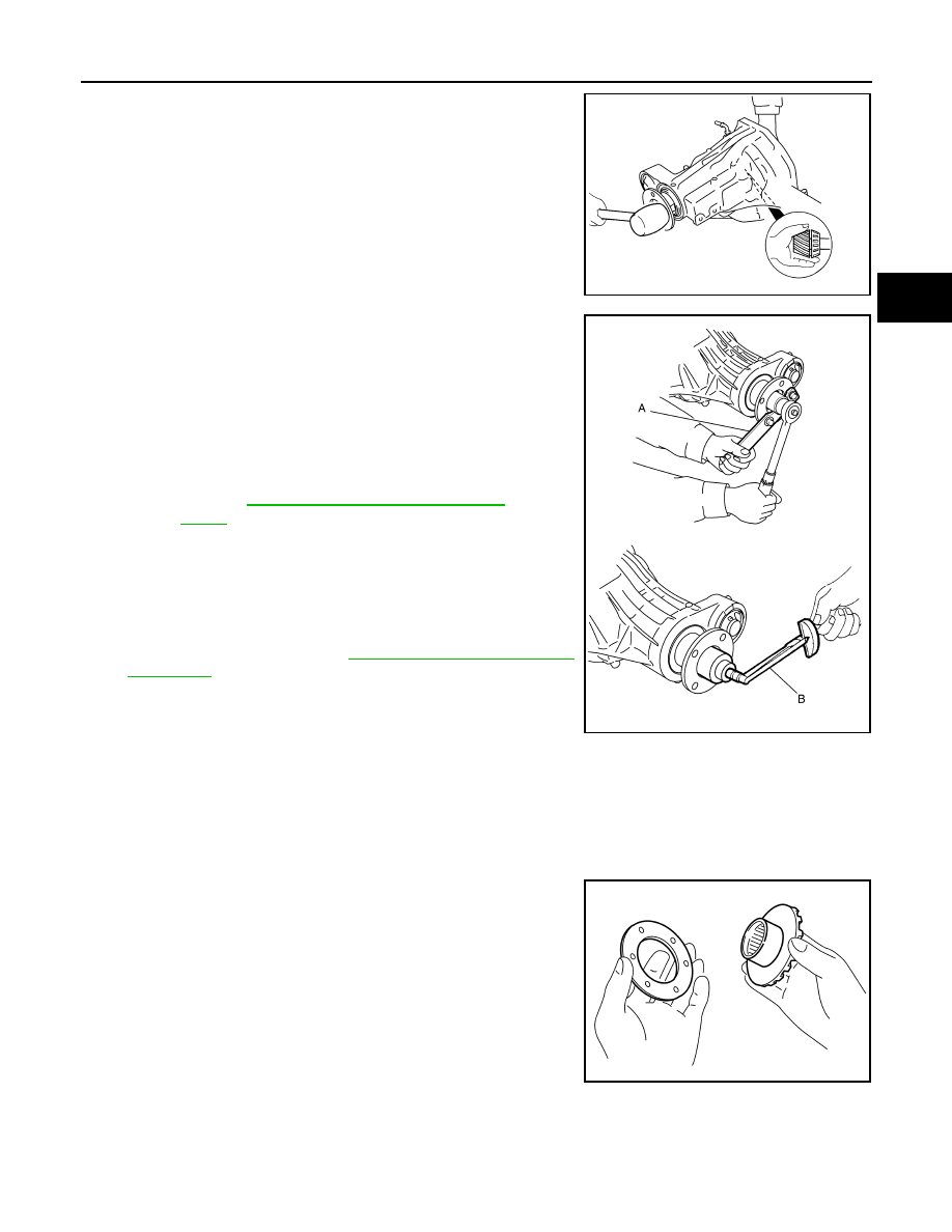
9. Install the companion flange to the drive pinion while aligning the

matching marks. Tap the companion flange until fully seated

using suitable tool.

10. Apply anti-corrosive oil to the threads of the drive pinion and the

seating surface of the new drive pinion lock nut. Then adjust the

drive pinion lock nut tightening torque using suitable tool (A),

and check the drive pinion bearing preload torque using Tool

(B).

CAUTION:

• Do not reuse drive pinion lock nut.

• Apply anti-corrosive oil to the threads of the drive pinion

and the seating surface of the new drive pinion lock nut.

• Adjust the drive pinion lock nut tightening torque to the

lower limit first. Do not exceed the drive pinion lock nut

specified torque. Refer to 

DLN-171, "Disassembly and

Assembly"

.

• If the drive pinion bearing preload torque exceeds the

specified value, replace collapsible spacer and tighten it

again to adjust. Do not loosen drive pinion lock nut to

adjust the drive pinion bearing preload torque.

• After adjustment, rotate drive pinion back and forth 2 to 3 times to check for unusual noise, rota-

tion malfunction, and other malfunctions.

11. Check companion flange runout. 
12. Install the differential case assembly.

Differential Assembly

1. Install side gear thrust washers with the same thickness as the

ones installed prior to disassembly, or reinstall the old ones on

the side gears.

SDIA2266E

Tool number

B: ST3127S000 (J-25765-A)

Drive pinion bearing preload torque:

Refer to 

DLN-187, "Inspection and Adjust-

ment"

WDIA0382E

SDIA0193J

DLN-184

< UNIT DISASSEMBLY AND ASSEMBLY >

[FRONT FINAL DRIVE: M205]

FRONT FINAL DRIVE

2. Install the side gears and side gear thrust washers into the dif-

ferential case.

3. Install the pinion mate thrust washers to the two pinion mate

gears. Then install the pinion mate gears with the pinion mate

thrust washers by aligning them in diagonally opposite positions

and rotating them into the differential case.

4. Install the pinion mate shaft and align the lock pin hole on the

pinion mate shaft with the lock pin hole on the differential case.

5. Measure the side gear end play. If necessary, select the appro-

priate side gear thrust washers.

6. Drive a new lock pin into the pinion mate shaft until it is flush

with the differential case using suitable tool.

CAUTION:

Do not reuse lock pin.

7. Align the matching mark of the differential case with the mark of

the drive gear, then place the drive gear onto the differential

case.

8. Install and tighten the new drive gear bolts to the specified

torque. Refer to 

DLN-171, "Disassembly and Assembly"

.

CAUTION:

• Make sure the drive gear back and threaded holes are

clean.

• Do not reuse drive gear bolts.

• Tighten new drive gear bolts in a crisscross pattern.

SDIA2025E

SDIA0195J

SPD030

SDIA2593E

SDIA2239E

FRONT FINAL DRIVE

DLN-185

< UNIT DISASSEMBLY AND ASSEMBLY >

[FRONT FINAL DRIVE: M205]

C

E

F

G

H

I

J

K

L

M

A

B

DLN

N

O

P

9. Press the new side bearing inner races to the differential case

using Tools.

CAUTION:

Do not reuse side bearing inner races.

10. Install side bearing adjusters into gear carrier.
11. Apply differential gear oil to the side bearings, and install the dif-

ferential case assembly with the side bearing outer races into

the gear carrier.

CAUTION:

Do not reuse side bearing outer race when replacing side

bearing inner race (replace as a set).

12. Install the side bearing caps with the matching marks aligned.

NOTE:

Do not tighten at this step. This allows further tightening of side

bearing adjusters.

13. Tighten each side bearing adjuster alternately turning drive gear.

14. Check and adjust tooth contact, backlash, drive gear runout and total preload torque. 

Recheck above items.

Tool number

A: KV38100300 (J-25523)
B: ST33081000 ( — )

SPD353

SPD527

PDIA0700E

SDIA2265E

DLN-186

< UNIT DISASSEMBLY AND ASSEMBLY >

[FRONT FINAL DRIVE: M205]

FRONT FINAL DRIVE

• After adjusting tooth contact and backlash secure side bearing

adjuster with screws and tighten side bearing cap bolt to the

specified torque. Refer to 

DLN-171, "Disassembly and Assem-

bly"

.

15. Apply multi-purpose grease to the lips of the new side oil seal. Then drive the new side oil seal in evenly to

the gear carrier using suitable tool.

CAUTION:

• Do not reuse side oil seal.

• Do not incline the new side oil seal when installing.

• Apply multi-purpose grease to the lips of the new side oil seal.

16. Install the extension tube with a new O-ring.

CAUTION:

• Do not reuse O-ring.

• If the extension tube is being replaced, install a new axle

shaft bearing.

17. Apply 3 mm (0.12 in) bead of sealant to the mating surface of

the carrier cover as shown.

• Use Genuine Silicone RTV or equivalent. Refer to 

GI-15,

"Recommended Chemical Products and Sealants"

.

CAUTION:

Remove any old sealant adhering to the mating surfaces.

Also remove any moisture, oil, or foreign material adhering

to the application and mating surfaces.

18. Install the carrier cover to the gear carrier. Tighten the bolts to

the specified torque. Refer to 

DLN-168, "Removal and Installa-

tion"

.

19. Install side shaft and side flange.

SDIA2263E

SDIA3205E

SDIA3204E


Content   ..  309  310  311  312   ..