Nissan Titan A60. Manual - part 238


  Index      Nissan     Nissan Titan A60 (2011 year) - Service and Repair Manual


Search            


Content   ..  236  237  238  239   ..


Nissan Titan A60. Manual - part 238


DLK-26

< DTC/CIRCUIT DIAGNOSIS >

POWER SUPPLY AND GROUND CIRCUIT

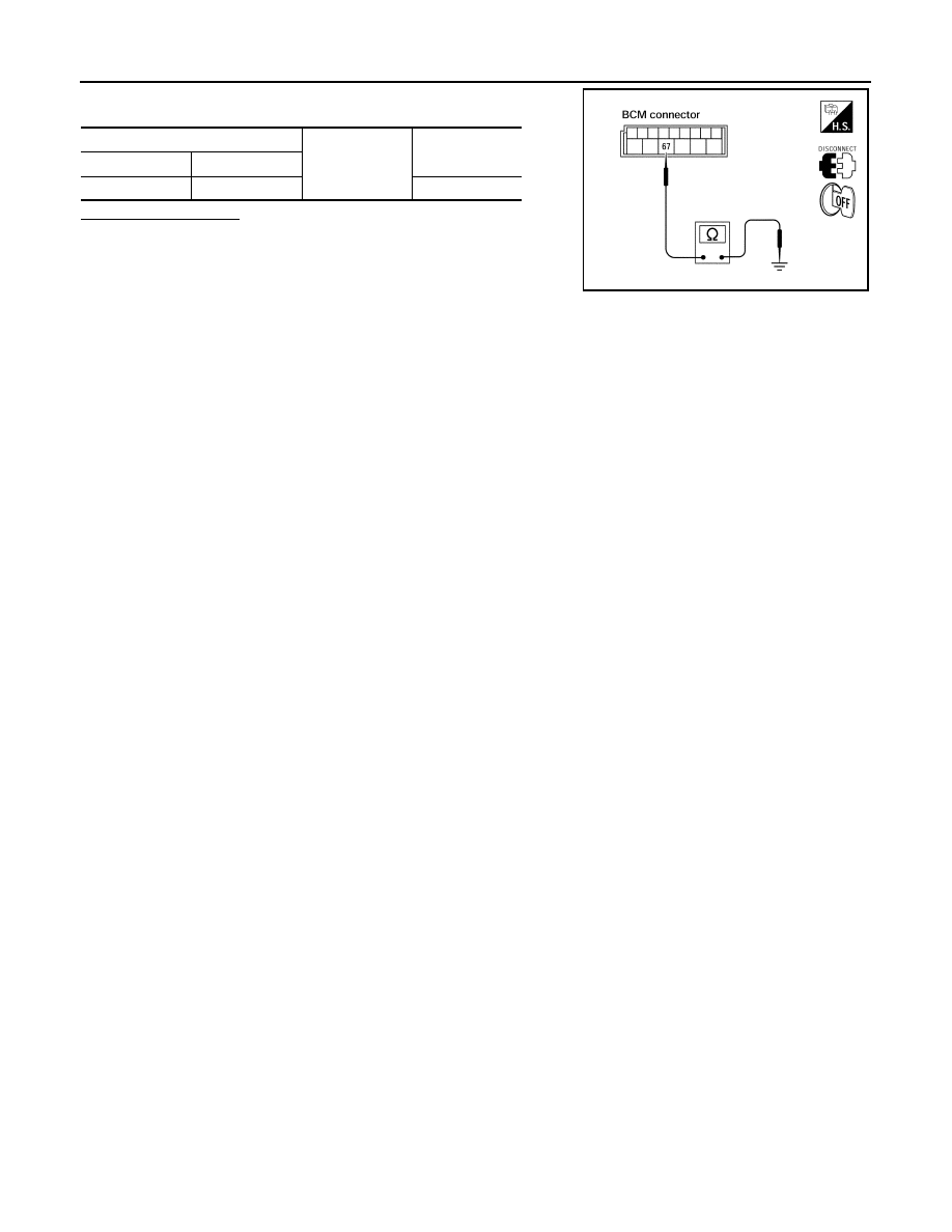
Check continuity between BCM harness connector and ground.

Does continuity exist?

YES

>> Inspection End.

NO

>> Repair or replace harness.

BCM

Ground

Continuity

Connector

Terminal

M20

67

Yes

LIIA0915E

DOOR SWITCH

DLK-27

< DTC/CIRCUIT DIAGNOSIS >

C

D

E

F

G

H

I

J

L

M

A

B

DLK

N

O

P

DOOR SWITCH

KING CAB
KING CAB : Description

INFOID:0000000006179189

Detects door open/close condition.

KING CAB : Component Function Check

INFOID:0000000006179190

1.

CHECK FUNCTION

With CONSULT-III

Check door switches in data monitor mode with CONSULT-III.

Is the inspection result normal?

YES

>> Door switch is OK.

NO

>> Refer to 

DLK-27, "KING CAB : Diagnosis Procedure"

.

KING CAB : Diagnosis Procedure

INFOID:0000000006179191

Regarding Wiring Diagram information, refer to 

DLK-77, "Wiring Diagram - King Cab"

.

1.

CHECK DOOR SWITCHES INPUT SIGNAL

With CONSULT-III

Check door switches ("DOOR SW-DR", "DOOR SW-AS") in DATA MONITOR mode with CONSULT–III. Refer

to 

DLK-20, "DOOR LOCK : CONSULT-III Function (BCM - DOOR LOCK)"

.

• When doors are open:

• When doors are closed:

Without CONSULT-III

Check voltage between BCM connector M18 or M19 terminals 12, 47 and ground.

Is the inspection result normal?

YES

>> Door switch circuit is OK.

NO

>> GO TO 2

2.

CHECK DOOR SWITCH CIRCUIT

Monitor item

Condition

DOOR SW-DR

CLOSE 

→ OPEN: OFF → ON

DOOR SW-AS

DOOR SW-DR

:ON

DOOR SW-AS

:ON

DOOR SW-DR

:OFF

DOOR SW-AS

:OFF

Connector

Item

Terminals

Condition

Voltage (V)

(Approx.)

(+)

(–)

M19

Door switches 

LH

47

Ground

Open

Closed

0

Battery voltage

M18

Door switches 

RH

12

LIIA1174E

DLK-28

< DTC/CIRCUIT DIAGNOSIS >

DOOR SWITCH

1. Turn ignition switch OFF.

2. Disconnect door switch and BCM.

3. Check continuity between door switch connector B8 (Front LH), B108 (Front RH) terminal 2, B73 (Rear

upper LH), B156 (Rear upper RH), B74 (Rear lower LH), B157 (Rear lower RH) terminal 1 and BCM con-

nector M18, M19 terminals 12, and 47.

4. Check continuity between door switch connector B8 (Front LH),

B108 (Front RH) terminal 2, B73 (Rear upper LH), B156 (Rear

upper RH), B74 (Rear lower LH), B157 (Rear lower RH) terminal

1 and ground.

Is the inspection result normal?

YES

>> GO TO 3

NO

>> Repair or replace harness.

3.

CHECK DOOR SWITCHES

Check continuity between door switch terminals.

Is the inspection result normal?

YES

>> Repair or replace harness.

NO

>> Replace door switch.

CREW CAB
CREW CAB : Description

INFOID:0000000006179192

Detects door open/close condition.

CREW CAB : Component Function Check

INFOID:0000000006179193

1.

CHECK FUNCTION

With CONSULT-III

Check door switches in data monitor mode with CONSULT-III.

Is the inspection result normal?

YES

>> Door switch is OK.

NO

>> Refer to 

DLK-29, "CREW CAB : Diagnosis Procedure"

.

2 - 47

:Continuity should exist

2 - 12

:Continuity should exist

1 - 47

:Continuity should exist

1 - 12

:Continuity should exist

2 - Ground

:Continuity should not exist

1 - Ground

:Continuity should not exist

LIIA1175E

Item

Terminals

Condition

Continuity

Door switches 

(front) 

2 – 3 

Open

No

Closed

Yes

Door switches (rear 

upper and lower)

1 – 2 

Open

No

Closed

Yes

WIIA0595E

Monitor item

Condition

DOOR SW-DR

CLOSE 

→ OPEN: OFF → ON

DOOR SW-AS

DOOR SW-RL

DOOR SW-RR

DOOR SWITCH

DLK-29

< DTC/CIRCUIT DIAGNOSIS >

C

D

E

F

G

H

I

J

L

M

A

B

DLK

N

O

P

CREW CAB : Diagnosis Procedure

INFOID:0000000006179194

Regarding Wiring Diagram information, refer to 

DLK-84, "Wiring Diagram - Crew Cab"

.

1.

CHECK DOOR SWITCHES INPUT SIGNAL

With CONSULT-III

Check door switches ("DOOR SW-DR", "DOOR SW-AS", "DOOR SW-RL", "DOOR SW-RR") in DATA MONI-

TOR mode with CONSULT–III. Refer to 

DLK-20, "DOOR LOCK : CONSULT-III Function (BCM - DOOR

LOCK)"

.

• When doors are open:

• When doors are closed:

Without CONSULT-III

Check voltage between BCM connector M18 or M19 terminals 12, 13, 47, 48 and ground.

Is the inspection result normal?

YES

>> Door switch circuit is OK.

NO

>> GO TO 2

2.

CHECK DOOR SWITCH CIRCUIT

1. Turn ignition switch OFF.

2. Disconnect door switch and BCM.

3. Check continuity between door switch connector B8 (Front LH), B108 (Front RH), B18 (Rear LH), B116

(Rear RH) terminal 2 and BCM connector M18, M19 terminals 12, 13, 47 and 48.

DOOR SW-DR

:ON

DOOR SW-AS

:ON

DOOR SW-RL

:ON

DOOR SW-RR

:ON

DOOR SW-DR

:OFF

DOOR SW-AS

:OFF

DOOR SW-RL

:OFF

DOOR SW-RR

:OFF

Connector

Item

Terminals

Condition

Voltage (V)

(Approx.)

(+)

(–)

M19

Front door 

switch LH

47

Ground

Open

Closed

0

Battery voltage

Rear door 

switch LH

48

M18

Front door 

switch RH

12

Rear door 
switch RH

13

LIIA1177E


Content   ..  236  237  238  239   ..