Nissan Titan A60. Manual - part 213
CHG
CHARGING SYSTEM
CHG-19
< SYMPTOM DIAGNOSIS >
C
D
E
F
G
H
I
J
K
L
B
A
O
P
N
SYMPTOM DIAGNOSIS
CHARGING SYSTEM
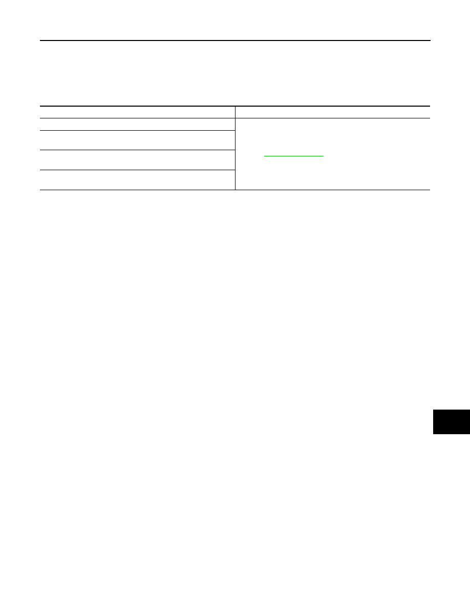
Symptom Table
INFOID:0000000006161771
Symptom
Reference
Battery discharged
The charge warning lamp does not illuminate when the ignition
switch is set to ON.
The charge warning lamp does not turn OFF after the engine
starts.
The charging warning lamp turns ON when increasing the engine
speed.