Nissan Titan A60. Manual - part 109
AV
COMMUNICATION SIGNAL CIRCUIT
AV-261
< DTC/CIRCUIT DIAGNOSIS >
[PREMIUM WITH NAVIGATION]
C
D
E
F
G
H
I
J
K
L
M
B
A
O
P
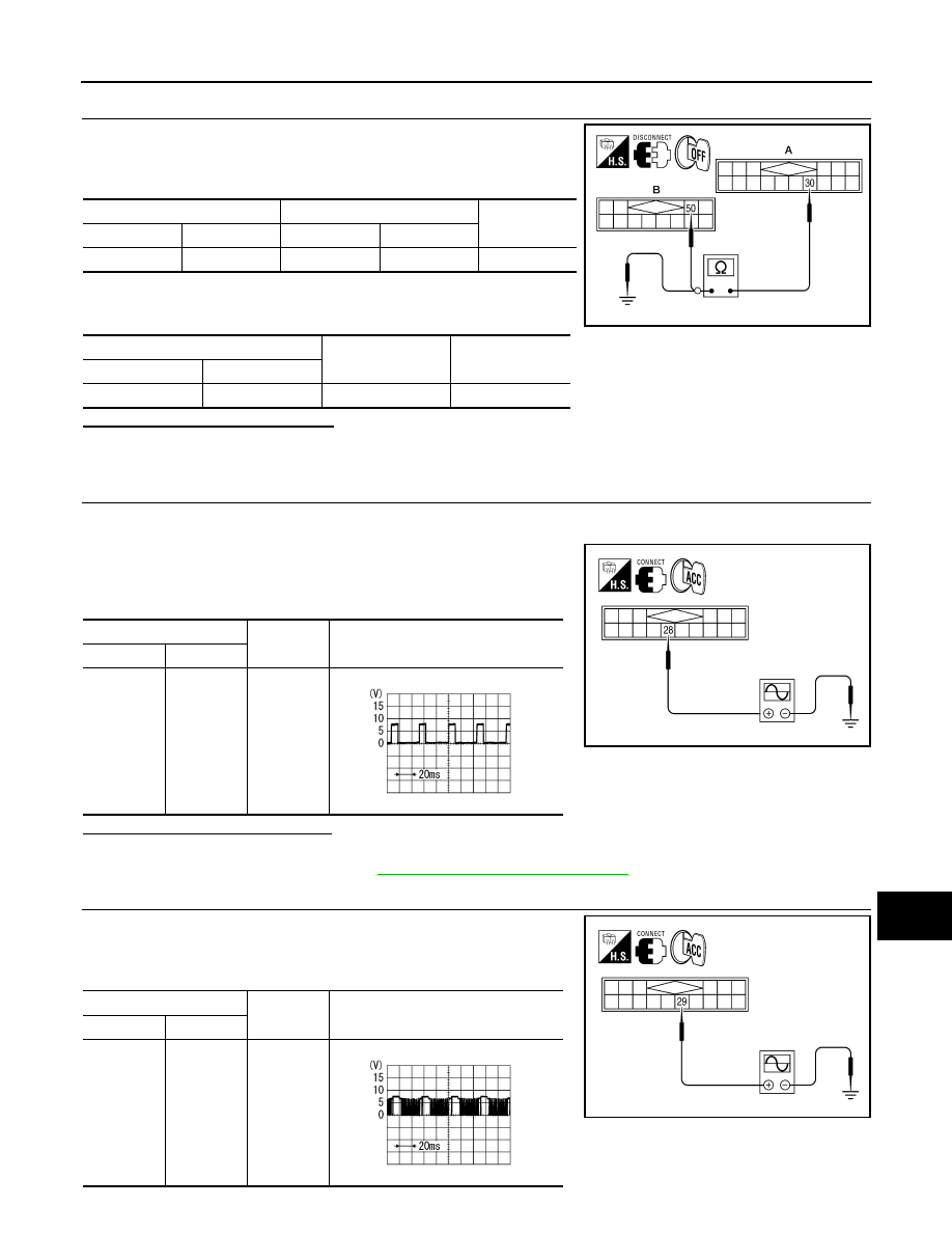
3.
CHECK HARNESS - RXD
1. Check continuity between satellite radio tuner (factory installed)
harness connector M41 (A) terminal 30 and audio unit harness
connector M42 (B) terminal 50.
2. Check continuity between satellite radio tuner (factory installed)
harness connector M41 (A) terminal 30 and ground.
Are continuity results as specified?
YES
>> GO TO 4.
NO
>> Repair harness or connector.
4.
CHECK REQ1 SIGNAL
1. Connect satellite radio tuner (factory installed) connector and audio unit connector.
2. Turn ignition switch to ACC
3. Check signal between satellite radio tuner (factory installed) har-
ness connector M41 terminal 28 and ground with CONSULT-III
or oscilloscope.
Are voltage readings as specified?
YES
>> GO TO 5.
NO
>> Replace audio unit. Refer to
AV-326, "Removal and Installation"
.
5.
CHECK TXD SIGNAL
Check signal between satellite radio tuner (factory installed) harness
connector M41 terminal 29 and ground with CONSULT-III or oscillo-
scope.
A
B
Continuity
Connector
Terminal
Connector
Terminal
M41
30
M42
50
Yes
A
—
Continuity
Connector
Terminal
M41
30
Ground
No
ALNIA0708GB
(+)
(-)
Reference signal
Connector
Terminal
M41
28
Ground
WKIA4544E
SKIB3825E
(+)
(-)
Reference signal
Connector
Terminal
M41
29
Ground
WKIA4545E
SKIB3824E